Double side image reading device

A technology for reading equipment and images, which can be applied to equipment, image communication, and electrical recording technology using charge patterns, etc. Motion stabilization effect

Inactive Publication Date: 2002-08-21
CANON KK
View PDF2 Cites 10 Cited by
  • Summary
  • Abstract
  • Description
  • Claims
  • Application Information

AI Technical Summary

Problems solved by technology

For this reason, it is necessary to construct a dedicated image reading device, but this will definitely greatly increase the cost.

Method used


Image

  • Double side image reading device
  • Double side image reading device
  • Double side image reading device

Examples


no. 1 example

[0040] The following is based on figure 1 3 illustrates a first embodiment of the present invention.

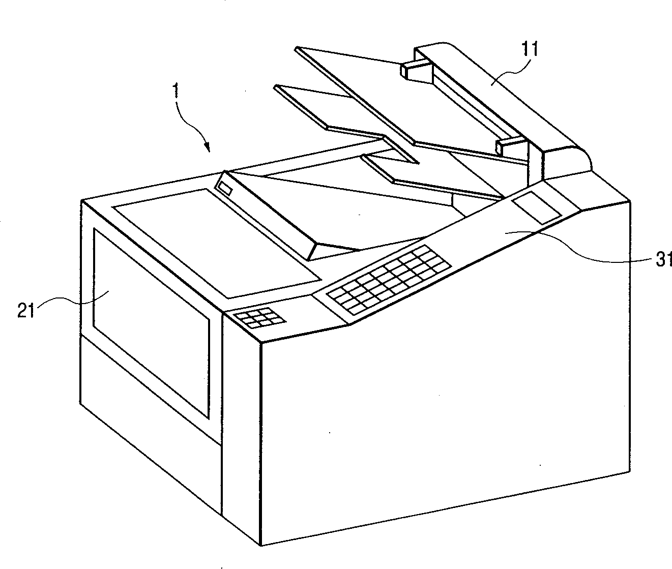
[0041] figure 1 is a perspective view of a facsimile machine showing a first embodiment of the present invention.

[0042] exist figure 1 Among them, facsimile machine 1 is made up of following parts: reading part 11, and it is used for reading original; Recording part 12, it is used for recording the image that reading part 11 reads or receives on recording paper; Operating part 31, It is used to allow the user to operate the facsimile machine; and a control section, not shown, which is used to control the sending / receiving operation and the copying operation. The double-sided image reading device of the present invention is applied to the reading section 11.

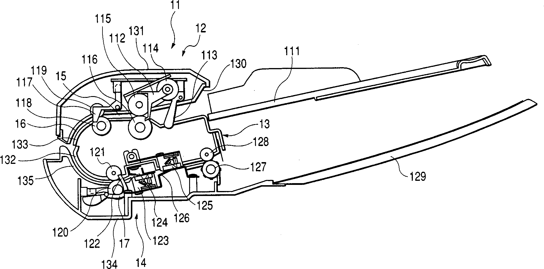
[0043] figure 2 is a cross-sectional view of the reading part 11, to which a double-sided image reading device is applicable, referring to figure 2 The structure and operation of the reading section 11 will be...

no. 2 example

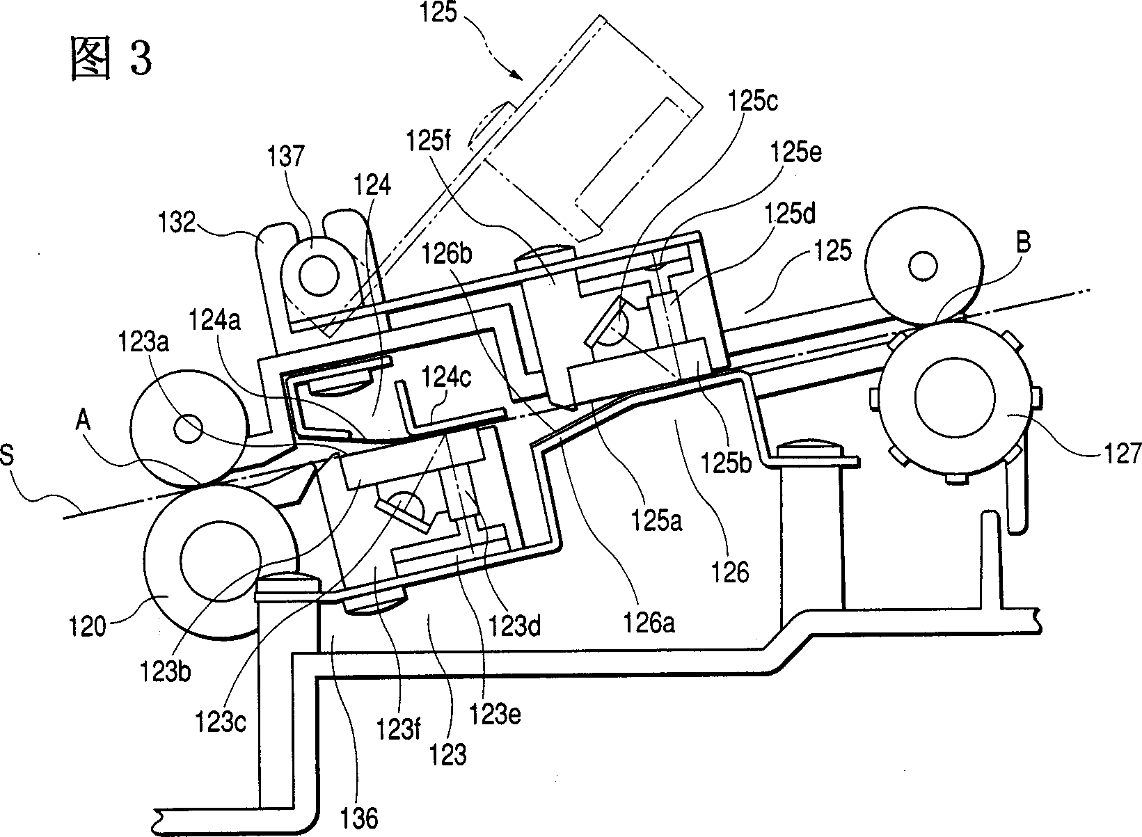
[0072] Figure 5 is a partially enlarged view of the reverse reading portion 125 showing the second aspect of the present invention.

[0073] Example.

[0074] exist Figure 5Among them, the sensor housing 125f of the reading part 125 on the reverse side is arranged so that the sensor housing 125f is elastically supported so as to be guided by a conductive plate spring 138 which is grounded (not shown) in the main body of the device, along the direction actually shown in FIG. The image reading surface 125a is displaceable in a direction perpendicular to the image reading surface 125a, whereby the image reading surface 125a is pushed against the reverse white reference 126.

[0075] Due to this structure, with Figure 3 and Figure 4 Compared with the supporting method shown in , there is no play or overflow between the respective mating parts, so that the reverse reading part 125 is prevented from being deviated along the conveying direction, and thus high-resolution reading...

no. 3 example

[0078] Figure 7 is a partially enlarged view of the reverse reading portion 125 showing the third aspect of the present invention.

[0079] Example.

[0080] exist Figure 7 Among them, the structure of the sensor housing 125f of the reading part 125 on the reverse side is such that the housing is elastically supported so as to be connected to the ground by an unshown conductive plate spring 139 in the device main body, The image reading surface 125a is displaceable in a vertical direction such that the image reading surface 125a is pushed against the reverse white reference 126 .

[0081] The plate spring 139 is connected and supported on almost the same plane as the image reading surface 125a, thus achieving the following effects.

[0082] That is, during the conveyance of the original S, friction between the image reading surface 125a and the original S generates a frictional force F toward the downstream in the conveying direction, but this frictional force F is usuall...


PUM


Abstract

A duplex image reading apparatus has a transportation path for transporting a sheet original to a reading region by an original transporting device, and first and second reading devices placed corresponding to respective transportation sides of the sheet original in the reading region of the transportation path, and is constructed in such structure that each of the first and second reading devices is of such a configuration that a color reference portion used as a color reference for reading is opposed to a reading portion while the color reference portion and the reading portion are placed on two sides with the transportation sides of the sheet original in between, wherein the first and second reading devices are arranged so that either one of the reading portion and the color reference portion is supported so as to be movable in a direction substantially perpendicular to an image reading surface of the reading portion.

Description

technical field [0001] The present invention relates to a double-sided image reading apparatus for reading images on both sides of an original conveyed by original conveying means. Background technique [0002] Among the conventional double-sided image reading devices, there has been proposed a structure in which two image reading devices are arranged in a fixed state on one side of the devices respectively on a curved conveying path, As described in Japanese Patent Application Lain-Open No. 2000-115452 (Japanese Patent Application Lain-Open No. 2000-115452). [0003] Another device has been proposed in which two image-reading devices are positioned almost opposite each other, one image-reading device being fixed and the other image-reading device being pushed against The fixed image reading device is as described in Japanese Patent Application Lain-Open No. 10-190938. [0004] However, in the above-mentioned former conventional example (Japanese Patent Application Lain-Op...

Claims


Application Information

Patent Timeline
Patent Type & Authority Applications(China)
IPC IPC(8): G03G15/00H04N1/12H04N1/193H04N1/203
CPCH04N1/121H04N2201/044H04N1/2032H04N1/203H04N1/193G03G15/00
Inventor 长谷川和彦沢田宏久
Owner CANON KK
Why Eureka
Try Eureka