Hydraulic control apparatus for hybrid vehicle

a technology of hydraulic control apparatus and hybrid vehicle, which is applied in the direction of dynamo-electric converter control, motor/generator/converter stopper, machine/engine, etc., can solve the problem of inability to ensure hydraulic pressure for the gearing mechanism, inability to inhibit the unrestricted control operation of oil pressure of the clutch, and steep increase in line pressur

Inactive Publication Date: 2006-05-09
HONDA MOTOR CO LTD +1
View PDF23 Cites 56 Cited by
  • Summary
  • Abstract
  • Description
  • Claims
  • Application Information

AI Technical Summary

Benefits of technology

[0011]In view of the above circumstances, an object of the present invention is to provide a hydraulic control apparatus for a hybrid vehicle which enables a smooth transmission of torque in a transmission in accordance with increase in the engine torque after the engine is started upon receiving an engine start request command during an idling stop operation.

Problems solved by technology

In the case in which a hydraulically-operated automatic transmission having a torque converter is employed in the above-mentioned hybrid vehicle, hydraulic pressure for a gearing mechanism in the automatic transmission is ensured by an oil pump that is driven by the engine when the engine runs; however, hydraulic pressure for the gearing mechanism cannot be ensured when the above-mentioned idling stop control is executed because the oil pump is also stopped and oil line pressure in the automatic transmission becomes zero.
When the engine is restarted upon receiving an engine starting command under conditions in which the oil line pressure is zero, consequently, the oil pump is also operated, and the oil line pressure steeply increases from zero, which may inhibit unrestricted control operation for oil pressure of a clutch.
As a result, the driving torque of the engine may not be smoothly transmitted to an output shaft of the vehicle, which may cause jolting of the vehicle.
Moreover, the clutch in the automatic transmission may slip when the oil line pressure steeply increases from zero, which may decrease the life of the clutch.
However, details of the control operations for oil line pressure and hydraulic pressure for the clutch associated with the automatic transmission are not disclosed at all in the above-mentioned documents.

Method used


Image

  • Hydraulic control apparatus for hybrid vehicle
  • Hydraulic control apparatus for hybrid vehicle
  • Hydraulic control apparatus for hybrid vehicle

Examples


Embodiment Construction

[0046]An embodiment of the hydraulic control device for a hybrid vehicle according to the present invention will be explained below with reference to FIGS. 1 to 11.

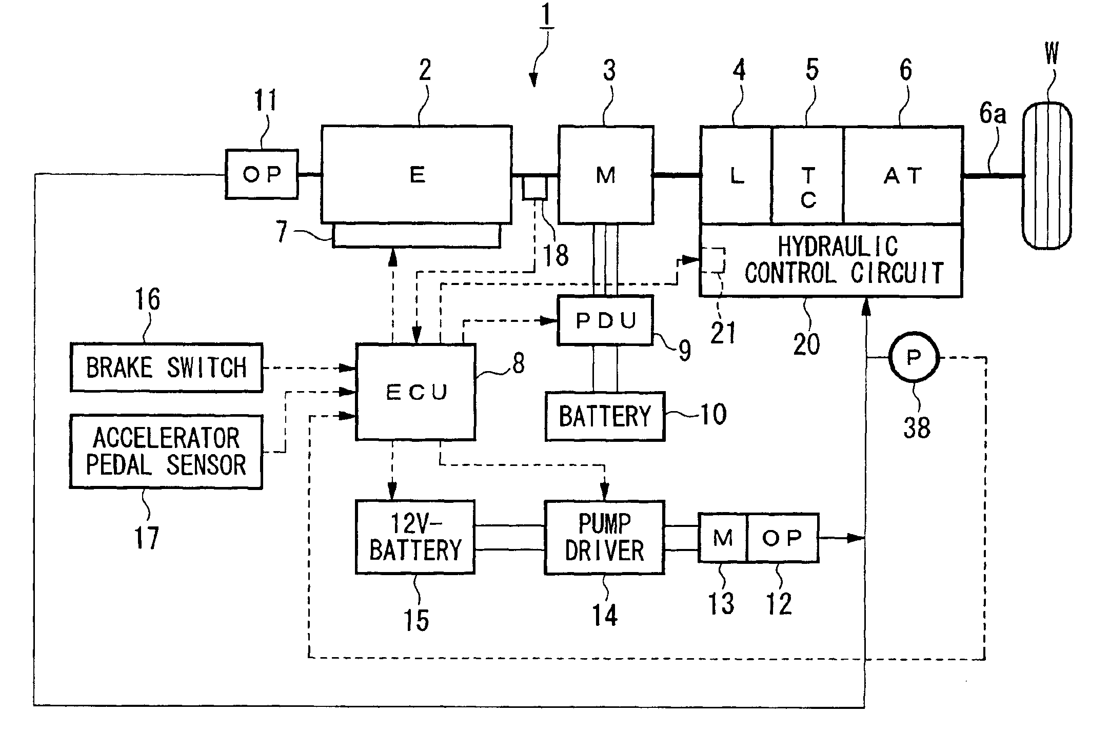
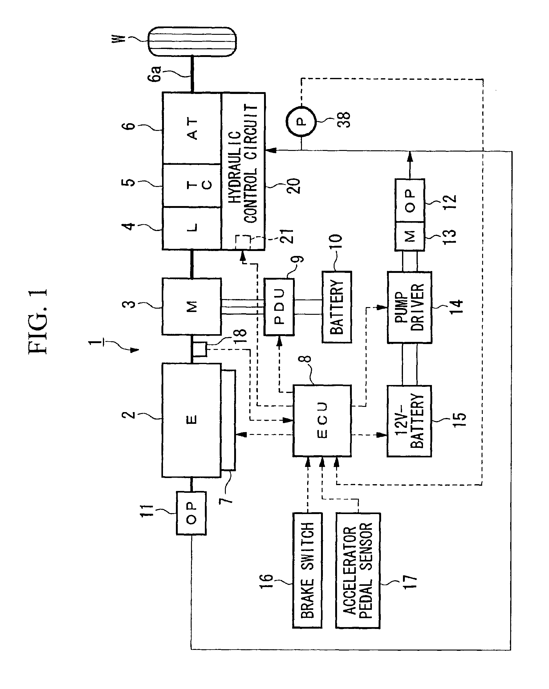
[0047]FIG. 1 is a schematic diagram showing a power transmission system of a hybrid vehicle 1 having the hydraulic control device according to the present invention.

[0048]In the hybrid vehicle 1, an engine 2 and a motor 3 (hereinafter referred to as a motor-generator) which is capable of generating electrical power are directly connected to each other, and at least one of the powers of the engine 2 and the motor-generator 3 is transmitted to output shafts 6a via a torque converter 4 having a lockup clutch 4 and via a multi-geared automatic transmission 6, and is further transmitted to driving wheels W via a differential gear mechanism (not shown) and the like.

[0049]The engine 2 is a multi-cylinder reciprocating engine, and is equipped with a fuel injection and ignition control device 7 which performs fuel injection contro...


PUM


Abstract

A hydraulic control apparatus for a hybrid vehicle, which enables a smooth torque transmission when an engine of the vehicle is started from an idling stop state. The hydraulic control apparatus includes an engine and a motor as power sources, a transmission having a torque converter, a clutch for a starting gear, an engine automatic stop and start device which is associated with the engine, a motor-driven oil pump for supplying oil pressure to the transmission, a brake pedal sensor, an accelerator pedal sensor, an engine revolution rate sensor. The oil pressure applied to the clutch is controlled to a level corresponding to a creeping torque when the engine is automatically stopped. When the brake pedal is released, the engine is automatically started, the accelerator pedal is not depressed, and the engine revolution rate is less than an idling revolution rate, the oil pressure applied to the clutch is maintained to the level corresponding to the creeping torque.

Description

BACKGROUND OF THE INVENTION[0001]1. Field of the Invention[0002]The present invention relates to a hydraulic control apparatus for an automatic transmission installed in a hybrid vehicle.[0003]2. Description of the Related Art[0004]In recent years, in order to reduce fuel consumption for driving an engine and to reduce the amount of exhaust gas that is produced by combusting the fuel, hybrid vehicles have been developed in which an engine and a motor capable of power generation (hereinafter referred to as a motor-generator) are associated with a power transmission mechanism that is connected to driving wheels of a vehicle, driving power during travel of the vehicle is augmented by the motor-generator as necessary, while on the other hand, the power being input to the driving wheels during deceleration of the vehicle is transmitted to the motor-generator so that the motor-generator performs a regenerative operation so as to convert the deceleration energy into regenerated energy whic...

Claims


Application Information

Patent Timeline
Patent Type & Authority Patents(United States)
IPC IPC(8): B60W10/08B60W20/00B60K6/485B60K6/547B60W10/00B60W10/04B60W10/06B60W10/10B60W10/18B60W10/184B60W10/30F02D17/00F02D29/00F02D29/02F02D29/06F16H61/00F16H61/02F16H63/50
CPCB60K6/485B60W10/06B60W10/10B60W10/30F16H61/0031Y10T477/24B60W2510/0638B60W2510/244B60W2540/10B60W2540/12F16H61/0021F16H61/0025F16H2312/14Y02T10/6226Y02T10/48Y10T477/865Y10T477/644Y10T477/743Y10T477/814Y10T477/747Y10T477/23Y10T477/87Y10T477/35B60L2240/441Y02T10/40Y02T10/62B60W30/18027
Inventor KURODA, SHIGETAKAMORISHITA, NAOHISAYAMAMOTO, KAZUHISA
Owner HONDA MOTOR CO LTD
Why Eureka
Try Eureka