Stably operable image-forming apparatus with improved paper conveying and ejecting mechanism

a technology of image-forming apparatus and ejector, which is applied in the direction of typewriters, printing, thin material processing, etc., can solve the problems of unstable paper conveyance, paper jams are more likely to occur, paper slippage on the conveyor belt, etc., and achieve the effect of improving image quality and conveying stably

Active Publication Date: 2006-07-27
RICOH KK
View PDF23 Cites 51 Cited by
  • Summary
  • Abstract
  • Description
  • Claims
  • Application Information

AI Technical Summary

Benefits of technology

[0033] According to the above-described image-forming apparatus, the conveyor belt is formed of a double-layer structure including a top (outer) layer, which is the insulating layer, and a bottom (inner) layer, which is the medium resistance layer. Accordingly, a sufficient electrostatic adhesive force can be obtained so that the paper can be conveyed stably and thus image quality can be improved.

Problems solved by technology

This results in the phenomenon that the sheet of paper slips on the conveyor belt.
Thus, if a conveyor belt with a low coefficient of friction μ, which is prevented from generating large conveying power, is employed in conveying a sheet of paper that requires large conveying power, the conveyance of the sheet of paper becomes unstable so that a paper jam is more likely to occur.
Therefore, when an image is formed on the paper, moisture included in the ink causes the paper to stretch.
Cockling may worsen to such an extent that, in the worst case, the paper comes into contact with the nozzle surface of the recording head.
As a result, not only the nozzle surface of the recording head but also the paper itself may be contaminated so that image quality is degraded.
Further, ink droplet misdirection may be caused by the effect of cockling.
Due to a recent demand for an increase in the printing region, however, some ink-jet printing apparatuses perform printing with paper being held by only one of the two pairs of rollers, which is a state that cannot guarantee the accuracy of paper feeding, in order to secure the printing region.
With paper being held by only one of the two pairs of rollers, however, the occurrence of paper flotation cannot be handled or the accuracy of paper feeding cannot be guaranteed because of insufficient conveying power.
This results in the degradation of image quality.
However, the conveyor belt is prone to have wrinkles in its chord part, and when the conveyor belt is rotated, the conveyor belt may undulate in its chord part.
Thus, even in the case of employing a conveyor belt, a decrease in the flatness of the conveyor belt causes a variation in the distance between a recording head and paper, thus degrading image quality.
As a result, a paper jam occurs.
In the conventional image-forming apparatus, however, the conveyor belt is a single-layer belt so that a sufficient electrostatic adhesive force to convey the paper stably cannot be obtained.

Method used


Image

  • Stably operable image-forming apparatus with improved paper conveying and ejecting mechanism
  • Stably operable image-forming apparatus with improved paper conveying and ejecting mechanism
  • Stably operable image-forming apparatus with improved paper conveying and ejecting mechanism

Examples


first embodiment

[0045] A description is given of a first embodiment of the present invention.

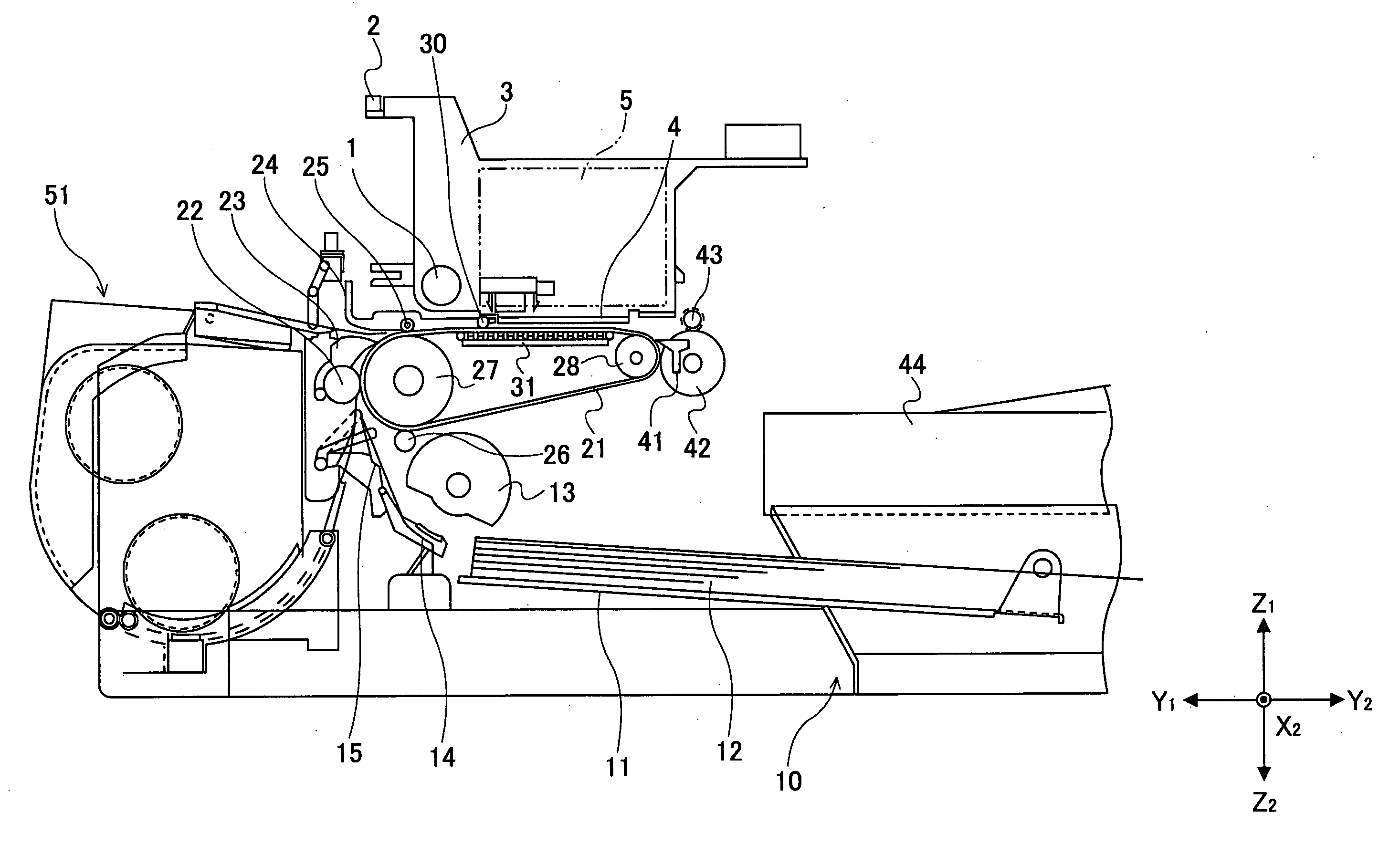
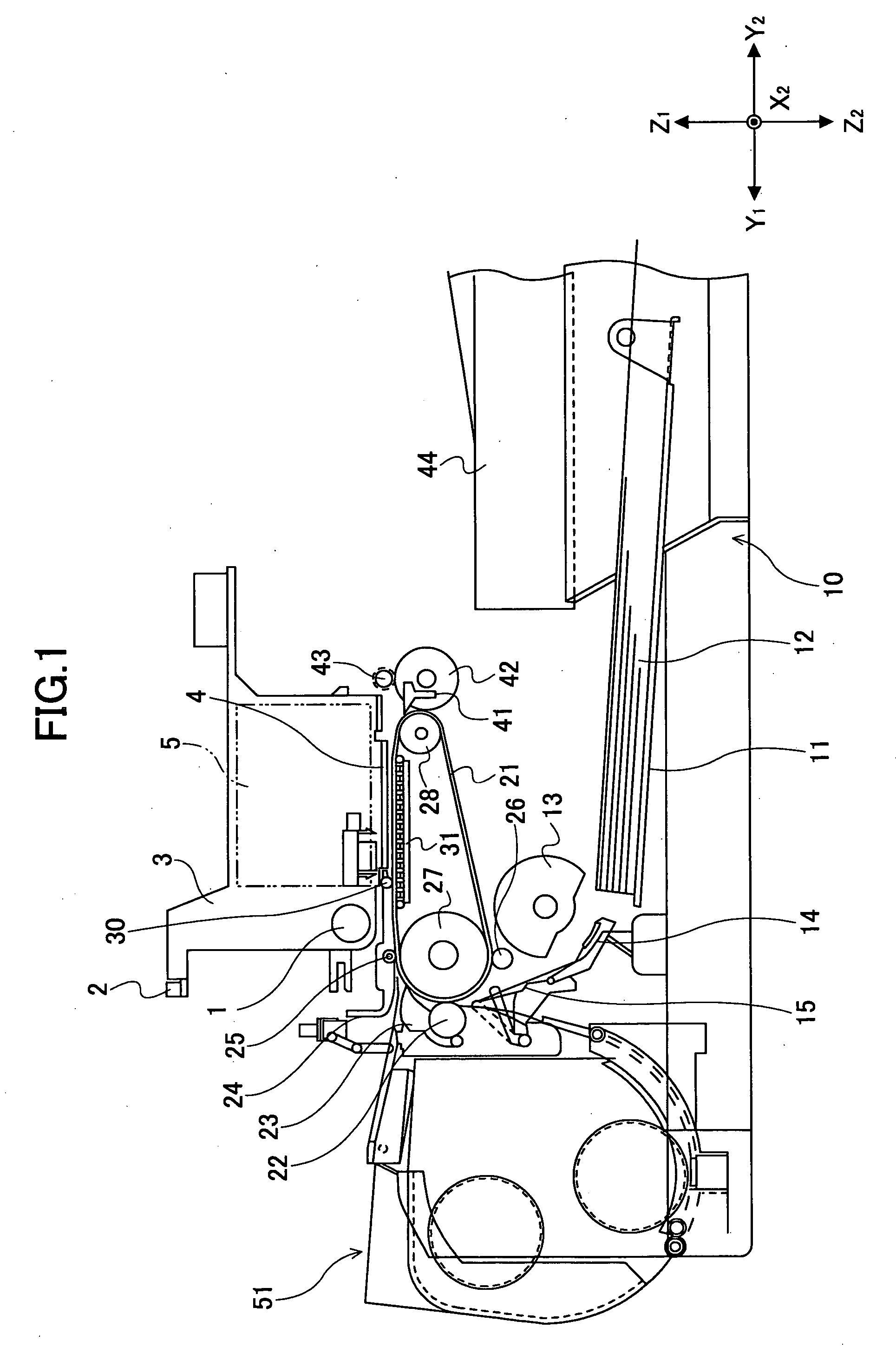
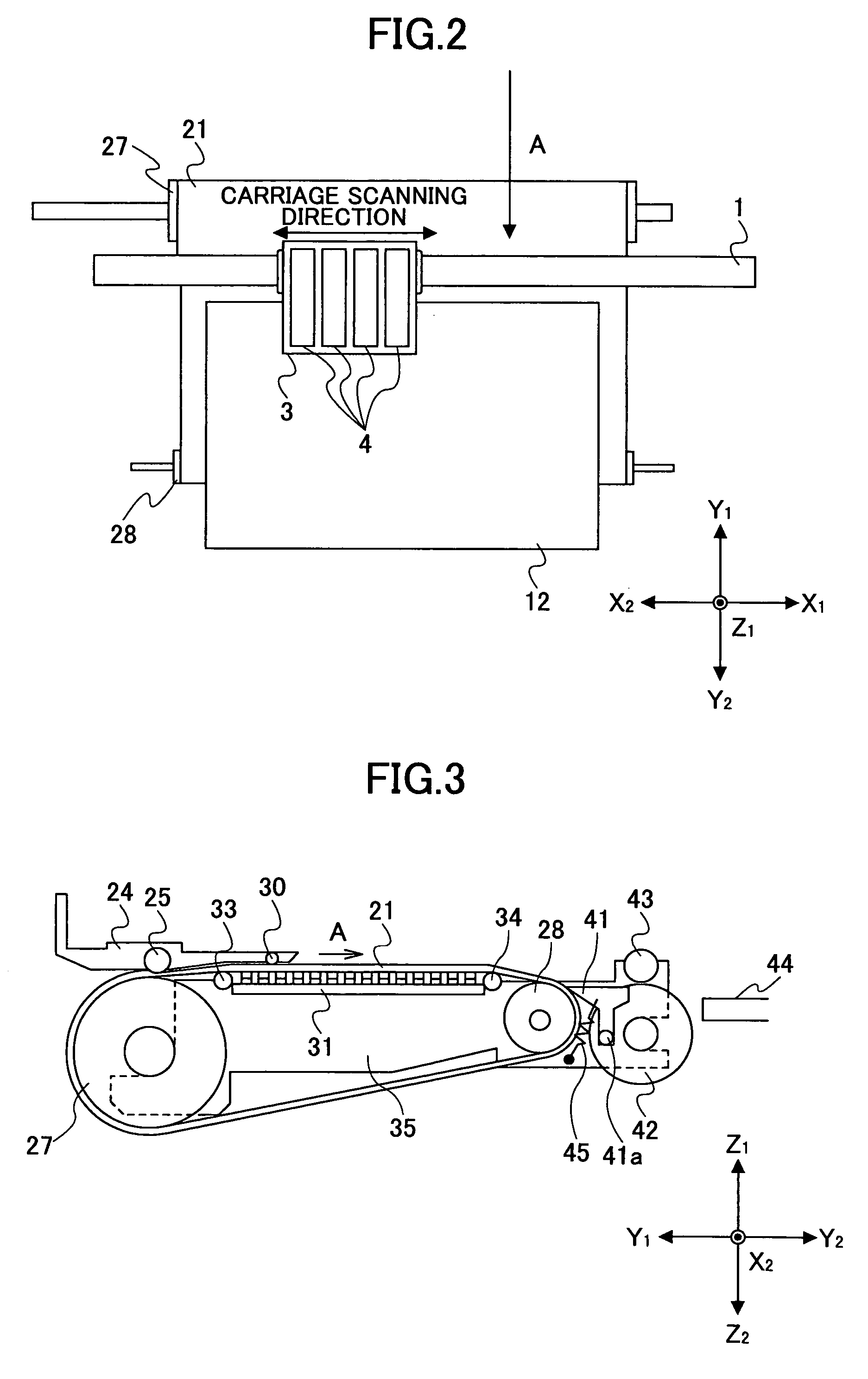
[0046]FIG. 1 is a diagram showing a configuration of an ink-jet recording apparatus as an image-forming apparatus according to the first embodiment of the present invention. FIG. 2 is a plan view of part of the ink-jet recording apparatus. FIG. 3 is a diagram showing part of a conveying part of the ink-jet recording apparatus.

[0047] Referring to FIGS. 1 and 2, the ink-jet recording apparatus of the present invention includes a guide rod 1 and a stay 2 provided as guide members extending between side plates (not shown in the drawings) on the X1 and X2 sides. The ink-jet recording apparatus holds a carriage 3 by the guide rod 1 and the stay 2 so that the carriage 3 is slidable in a main scanning direction or the X1 and X2 directions. A main scanning motor (not shown in the drawings) drives the carriage 3 so that the carriage 3 moves and scans in the X1 and X2 directions.

[0048] The carriage 3 includes a rec...

second embodiment

[0084] Next, a description is given of a second embodiment of the present invention. The same elements as those of the first embodiment are referred to by the same numerals.

[0085] Referring to FIG. 9, the separation claw 41 is supported pivotably by the support shaft 41a so as to be contactable with (be able to come into contact with) and separable from the surface of the conveyor belt 21. In the second embodiment, a plunger 61 for causing the separation claw 41 to come into contact with and separate from the surface of the conveyor belt 21 is provided instead of the elastic body 45. A main control part 63 drives and controls the plunger 61 through a driver 64 based on a detection signal supplied from an edge detection sensor 62 detecting the edge (leading edge) of the sheet of paper 12. The edge detection sensor 62 is provided to the carriage 3.

[0086] According to this configuration, the plunger 61 may be driven to cause the separation claw 41 to come into contact with the surfac...


PUM

PropertyMeasurementUnit
thicknessaaaaaaaaaa
thicknessaaaaaaaaaa
volume resistivityaaaaaaaaaa

Abstract

An image-forming apparatus includes an endless conveyor belt, a counter roller, and a clutch part. The endless conveyor belt is rotatable to convey paper with a surface of the conveyor belt being charged. The counter roller holds the paper between the conveyor belt and the counter roller and conveys the paper. The clutch part is caused to slip by the difference in velocity between the conveyor belt and the counter roller. The counter roller is driven through the clutch part.

Description

TECHNICAL FIELD [0001] The present invention relates generally to image-forming apparatuses, and more particularly to an image-forming apparatus that uses a conveyor belt to convey a sheet of paper. BACKGROUND ART [0002] An ink-jet printer is a well-known one of image-forming apparatuses (or image-recording apparatuses) such as printers, facsimile machines, and copiers. The ink-jet printer performs recording on a recording medium such as paper (recording paper) by ejecting ink from a recording head. The recording medium is not limited to paper. The recording medium refers to a medium on which an image is formable. The recording medium may be an OHP (overhead projector) sheet, for instance. The ink-jet printer can record a high-definition image at high speed with low running cost and reduced noise. Further, the ink-jet printer enjoys another advantage of easiness in recording a color image using multiple color inks. [0003] A well-known ink-jet head includes, as a part for generating ...

Claims


Application Information

Patent Timeline
Patent Type & Authority Applications(United States)
IPC IPC(8): B41J2/01B41J11/00B41J13/10B65H5/00
CPCB41J11/007B41J11/0095B41J13/103B41J13/106B65H5/004B65H2301/44312B65H2301/44334B65H2403/72B65H2404/262B65H29/56
Inventor SAKUMA, HIDEOMIIMOTO, SHINJIITOH, YOHICHIYASUDA, HIROSHIISHII, AKIRA
Owner RICOH KK
Why Eureka
Try Eureka