Linear Drive Assembly with Rotary Union for Well Head Applications and Method Implemented Thereby

Inactive Publication Date: 2008-10-23
APPLIED ENERGY PRODS
View PDF3 Cites 8 Cited by
  • Summary
  • Abstract
  • Description
  • Claims
  • Application Information

AI Technical Summary

Benefits of technology

[0011]It is a further object of the present invention to provide a drive assembly and method for a pump that eliminates torque forces resulting from offset side mounting of the drive asse

Problems solved by technology

Problems result from this solution to providing a rotary seal, however.
For example, if the carbon-impregnated rope is compressed too much against the polish rod, abrasion will form a groove in the polish rod which can cause severe leakage of the system.
Such leakage is not only uneconomical, but it may also result in environmental damage.
Indeed, such wells are monitored for leakage and any discov

Method used


Image

  • Linear Drive Assembly with Rotary Union for Well Head Applications and Method Implemented Thereby
  • Linear Drive Assembly with Rotary Union for Well Head Applications and Method Implemented Thereby
  • Linear Drive Assembly with Rotary Union for Well Head Applications and Method Implemented Thereby

Examples


Example

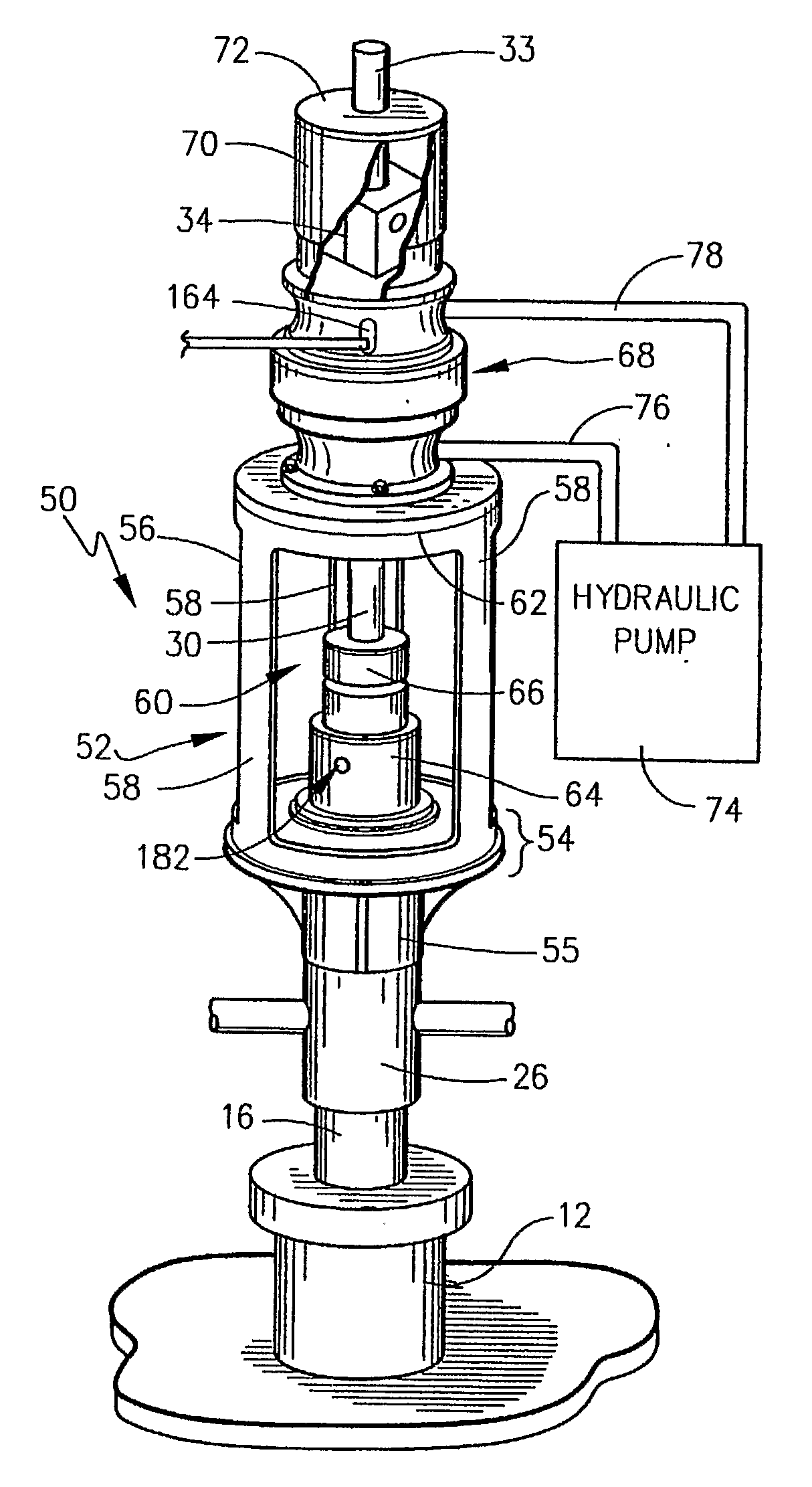
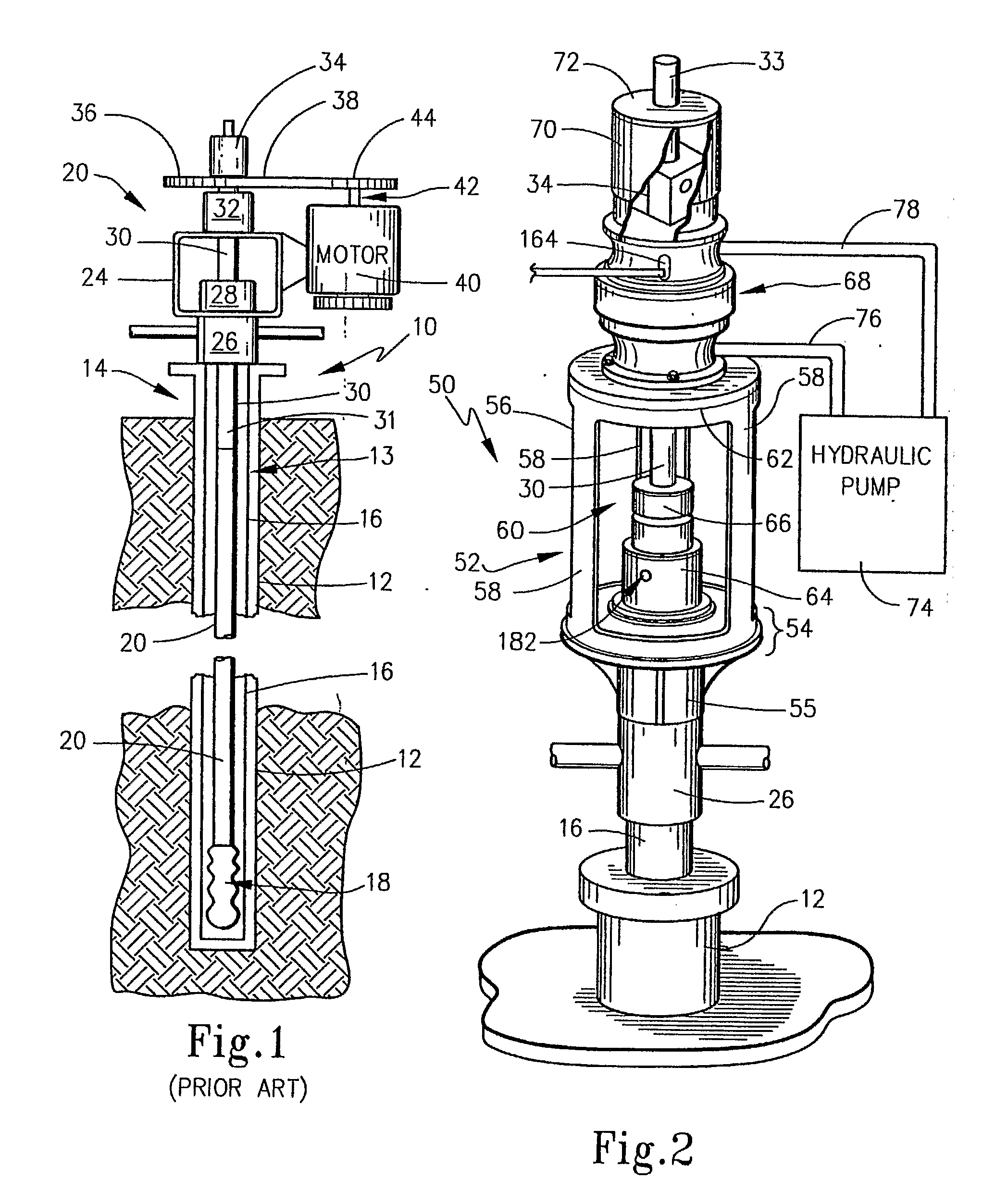
[0034]The present invention broadly concerns drive assemblies and methods for driving a progressive cavity pump that is located down hole in a well. Here, such wells are known to be provided having a casing interior and a sucker rod located in a delivery tube within the casing interior whereby rotation of the sucker rod acts to rotate the progressive cavity pump. In the exemplary embodiments, the drive assembly is a linear drive having an output shaft that is coaxial with a polish rod that is connected to the sucker rod. Another aspect of the exemplary embodiments of the present invention includes a rotary union that substantially seals the production flow through the delivery tube and that includes a friction cap that seals against the polish rod with the rotary union providing a rotary seal whereby the polish rod may be rotated in a substantially sealed rotation in the rotary union.

[0035]In order to introduce the aspects of the present invention, reference may be first made to FIG...


PUM


Abstract

A drive assembly for a progressive cavity pump includes a frame supported by the wel piping and a polish rod connected to the sucker rod. The polish rod is received by a rotary union formed by a sleeve portion rotatable with respect to a body portion with a seal structure that seals the sleeve and body portions during rotation. A mechanical drive, such as a hydraulic motor, electric motor or engine, has an output shaft that is linear with the polish rod and that has an axial passageway which receives the polish rod. A coupler mechanically couples an upper portion of the polish rod to the output shaft. The invention also includes a method of rotating a progressive cavity pump by this assembly.

Description

FIELD OF THE INVENTION[0001]The present invention broadly concerns wells and drive assemblies therefore along with methods for pumping fluids from a down hole location in the well to the surface. More particularly, the present invention is directed to a linear drive assembly and pump assemblies incorporating in the same so that torque forces on the assembly are reduced. The invention specifically is directed to a drive assembly for a progressive cavity pump. The invention also relates to a rotary seal that may be used with these and other pump assemblies. Further, the invention is directed to methods accomplished by these pump assemblies.BACKGROUND OF THE INVENTION[0002]Since ancient days, humankind has been known to settle around convenient sources of fresh water, such as lakes, rivers, streams, springs and the like. These sources are normally exposed at the surface of the earth for ready access. However, early on it was further learned that subterranean water supplies could be tap...

Claims


Application Information

Patent Timeline
IPC IPC(8): E21B43/00
CPCE21B43/126
Inventor WALDENSTROM, CARL G.KEFFER, MICHAEL A.
Owner APPLIED ENERGY PRODS
Why Eureka
Try Eureka