
Joint Ic Card And Wireless Transceiver Module For Mobile Communication Equipment

a wireless transceiver and mobile communication technology, applied in the field of integrated circuits, can solve the problems of lack of teaching and prior art has failed to address this problem

Inactive Publication Date: 2008-10-23
TELECOM ITALIA SPA
View PDF6 Cites 143 Cited by
  • Summary
  • Abstract
  • Description
  • Claims
  • Application Information

AI Technical Summary

Benefits of technology

This patent proposes adding a chip to allow communication between an IC card chip and a transceiver without requiring separate design and layout for these components. Existing chips can be reused for both purposes, saving time and money for developers. Additionally, individual functions on the IC card can be upgraded separately from the overall interface to the device.

Problems solved by technology

This patent describes a technical problem related to integrating multiple functionalities into a single simcard for a mobile device. Current solutions require costly customization of components, but there is no effective way to utilize existing infrastructure without sacrificing performance. Therefore, the objective of this patent is to enable seamless communication between the host device's standard simcard and external transceivers while reducing development expenses.

Method used


Image

  • Joint Ic Card And Wireless Transceiver Module For Mobile Communication Equipment
  • Joint Ic Card And Wireless Transceiver Module For Mobile Communication Equipment
  • Joint Ic Card And Wireless Transceiver Module For Mobile Communication Equipment

Examples


Embodiment Construction

[0025]The invention will now be described in greater detail assuming, by way of non-limiting example, that the transceiver to be mounted on the SIM card is a ZigBee™ transceiver. ZigBee™ devices are of particular interest due to their features of low energy consumption and to their capability of self-reconfiguration into an ad hoc network, allowing an indirect information transfer from one network node (i.e. a transceiver) to another one. Such features, jointly to the possibility of integrating both the analogue transmission function and the whole communication protocol onto the same chip, make more and more interesting the application of such components within existing devices such as the SIM cards.

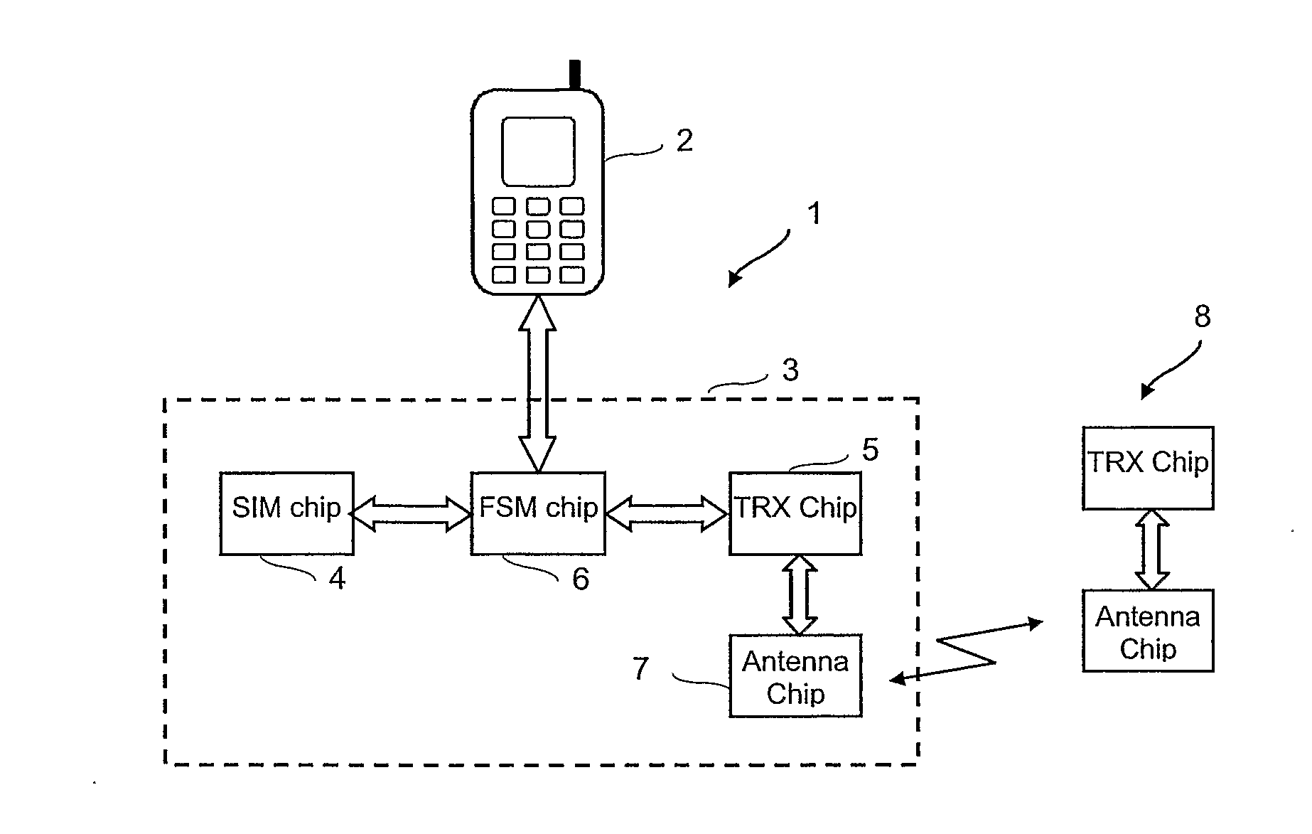
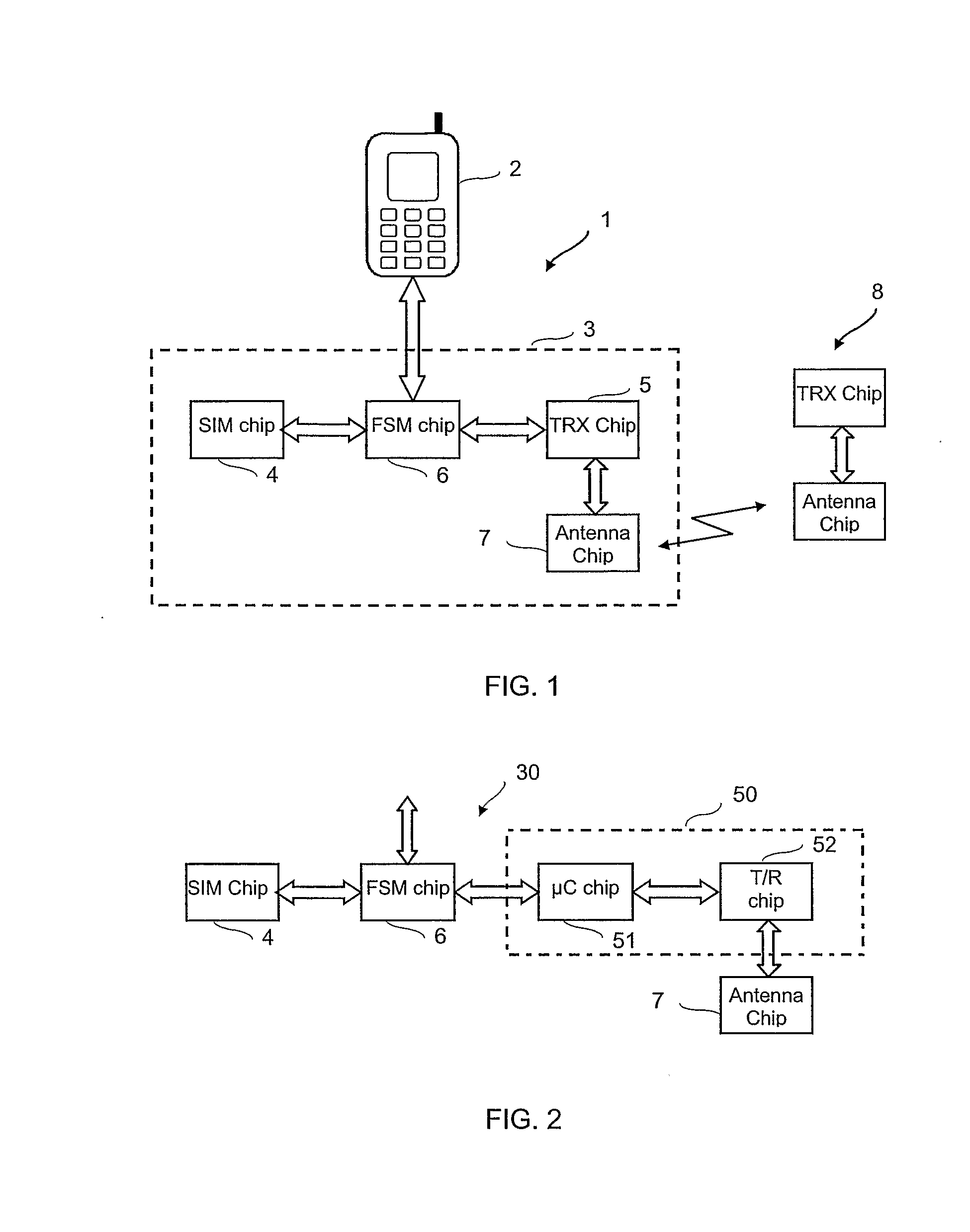
[0026]Referring to FIG. 1, a telecommunication equipment, generally shown at 1, includes a terminal 2, e.g. a cellular phone, equipped with a SIM card 3, which, according to the invention, is to perform both the functions of a standard SIM and of a ZigBee™ transceiver. For sake of clarit...


PUM


Abstract

An integrated circuit card for a mobile terminal incorporates a radio transceiver module intended for communications that do not pass through the mobile network. To allow using, for the chip of the IC card and the radio transceiver module, the same chips as would be used for conventional IC cards and transceivers not integrated together, the IC card further includes a finite state machine chip interconnecting the IC card chip and the chip(s) of the transceiver module so that they have access to the card contacts establishing connection between the card and the terminal.

Description


Claims


Application Information

Patent Timeline
Owner TELECOM ITALIA SPA
Learn More