Eyeglasses with electrical components

a technology of eyeglasses and electrical components, applied in the field of eyeglasses, can solve the problems of reducing the chance that the electrical components adversely affect the style of the frame, and achieve the effect of convenient operation

Active Publication Date: 2006-02-02
INGENIOSPEC
View PDF47 Cites 241 Cited by
  • Summary
  • Abstract
  • Description
  • Claims
  • Application Information

AI Technical Summary

Benefits of technology

[0007] The present invention provides a pair of glasses with one or more embedded or partially embedded electrical components. In a number of the embodiments of the invention, with one or more electrical components in the glasses,

Problems solved by technology

Further, the chance for the electrical components to

Method used


Image

  • Eyeglasses with electrical components
  • Eyeglasses with electrical components
  • Eyeglasses with electrical components

Examples


embodiment 200

[0059] In one embodiment, the length of the tube is adjustable. FIG. 3 shows such an embodiment 200 of a pair of glasses with a retractable tube 202. In the figure, the tube is shown to be in its extended position.

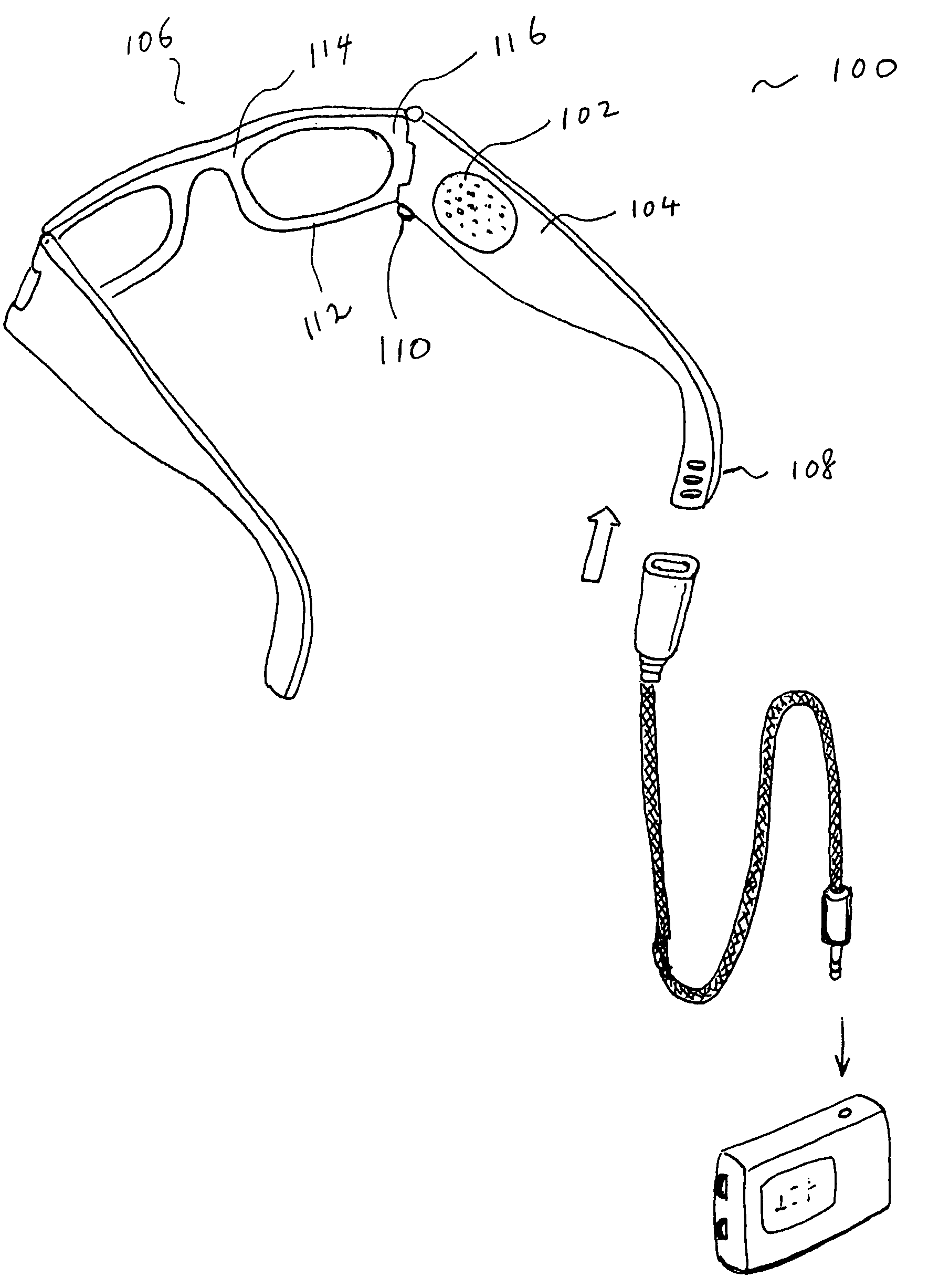
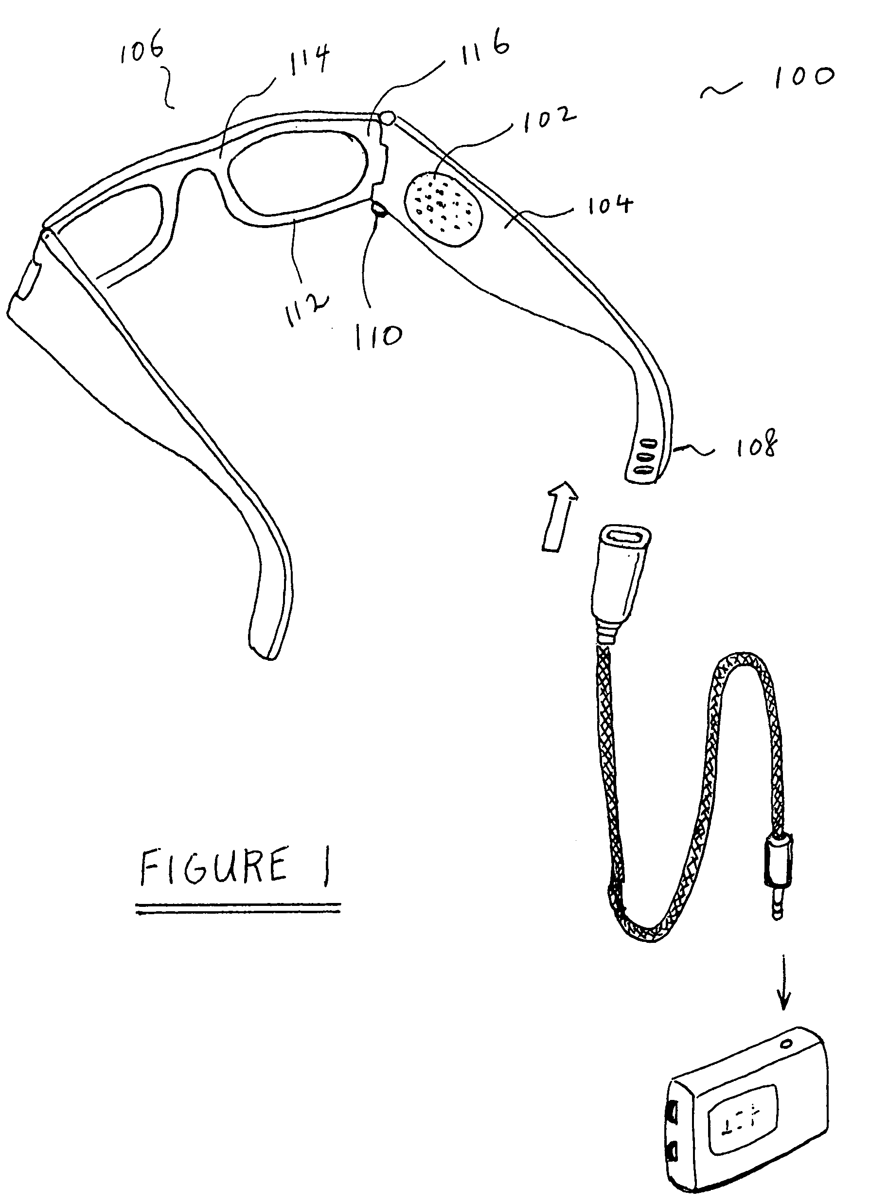
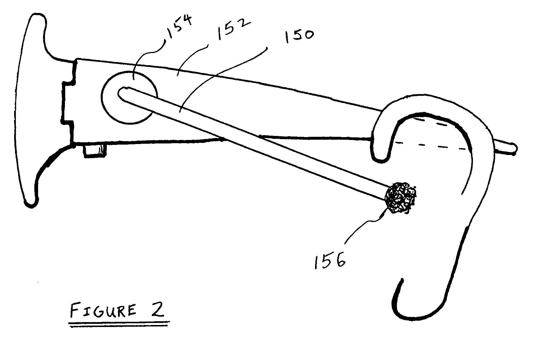
[0060] To further enhance sound coupling, in one approach, there is a plug 156 at the end of the tube for inserting into an ear of the user. The plug can be an ear bud. The plug can provide a cushion, foam rubber or other materials. Such materials give comfort and / or enhance sound coupling to the ear canal.

[0061] In another approach, there is a funnel at the output of the speaker. FIG. 4 shows the cross section of such a funnel from a speaker at a temple region of the glasses. As shown in FIG. 4, the speaker 254 sits on a speaker frame 252, and the speaker 254 is electrically connected to a circuit board 256. As sound is generated from the speaker 254, the sound propagates to a tube 258 through a structure 260 in the shape of a funnel. Such a structure helps guide the sou...

embodiment 950

[0181]FIG. 19 shows another embodiment 950 where one or more electrical components are at least partially embedded in a night cap 952. In one embodiment, the cap 952 is at least partially made of fabric. In another embodiment, the cap 952 is entirely made of fabric. The cap includes a wrapping mechanism. When the cap is worn, the wrapping mechanism holds the cap onto the head of the user, and allows the cap to have a relatively tight and comfortable fit over the head of the user. Again the wrapping mechanism can be an elastic band at the base 962 of the cap 952. Or, the wrapping mechanism can include clips or Velcro as previously described.

[0182] The cap can include at least one speaker 954, which is at least partially embedded in the cap 952. When the cap 952 is worn by a user, the speaker 954 is positioned close to and facing one of the ears of the user. The speaker 954 can, for example, be electrically connected through a connector to a device 962 in a pocket 960 on the cap 952. ...


PUM


Abstract

A pair of glasses with one or more electrical components partially or fully embedded in the glasses is disclosed. In one embodiment, a pair of glasses includes a speaker and an electrical connector, both at least partially embedded in the glasses, with the speaker and the connector electrically coupled together by an electrical conductor. In another embodiment, a pair of glasses includes a storage medium and an electrical connector. In yet another embodiment, a pair of glasses includes a speaker, a coder/decoder, a processor and a storage medium. The glasses can serve as a multimedia asset player. In a further embodiment, some of the electrical components are in a base tethered to a pair of glasses. Instead of just receiving signals, in one embodiment, a pair of glasses also has a microphone and a wireless transceiver. In another embodiment, a pair of glasses includes a preference indicator that allows a user to indicate the user's preference regarding, for example, what is being output by the glasses. In yet another embodiment, there can be one or more control knobs on the glasses. In a further embodiment, a pair of glasses includes a camera and electrical components for wireless connection. In yet a further embodiment, a pair of glasses includes a sensor.

Description

CROSS-REFERENCE TO RELATED APPLICATIONS [0001] This application is a continuation-in-part of U.S. patent application Ser. No. 10 / 964,011, filed Oct. 12, 2004, and entitled “TETHERED ELECTRICAL COMPONENTS FOR EYEGLASSES,” which is hereby incorporated herein by reference, which in turn claims priority to each of: (i) U.S. Provisional Patent Application No. 60 / 509,631, filed Oct. 9, 2003, and entitled “TETHERED ELECTRICAL COMPONENTS FOR EYEGLASSES,” which is hereby incorporated herein by reference; (ii) U.S. Provisional Patent Application No. 60 / 527,565, filed Dec. 8, 2003, and entitled “ADAPTABLE COMMUNICATION TECHNIQUES FOR ELECTRONIC DEVICES,” which is hereby incorporated herein by reference; (iii) U.S. Provisional Patent Application No. 60 / 562,798, filed Apr. 15, 2004, entitled “EYEWEAR WITH ULTRAVIOLET DETECTION SYSTEM,” and which is hereby incorporated herein by reference; (iv) U.S. Provisional Patent Application No. 60 / 583,169, filed Jun. 26,2004, entitled “ELECTRICAL COMPONENTS...

Claims


Application Information

Patent Timeline
IPC IPC(8): G02C5/00G02C1/00G02C5/14G02C7/10G02C11/00G02C11/06
CPCG02C5/001G02C11/10G02C11/06
Inventor HOWELL, THOMAS A.CHAO, DAVIDTHOMAS, C. DOUGLASSTONG, PETER P.
Owner INGENIOSPEC
Why Eureka
Try Eureka