Method For Dynamically Selecting Antenna Array Architecture

Inactive Publication Date: 2008-11-13
SHANGHAI ULTIMATE POWER COMM TECH
View PDF22 Cites 2 Cited by
  • Summary
  • Abstract
  • Description
  • Claims
  • Application Information

AI Technical Summary

Benefits of technology

[0011]According to the method of the present invention for dynamically selecting antenna array architecture, array elements whose number is smaller than that of the whole array elements are selected from the selected basic antenna array architecture to form a new antenna array architecture and when the number of the array elements is comparatively fixed, different array elements are selected for different slots of different transmission time intervals to form different antenna array architectures so that it is simple to realize and has better flexibility and can guarantee the antenna array can receive user signals at different arriving angles, i.e. even the antenna array architecture at some slots shadows a signal at some arriving angle, with the change of slots, each array elements in the antenna array can receive arriving signals more reasonably so as to avoid possible blind area problems of the fixed antenna array architecture, which further improves the performance of the base station system and the reliability of receiving user signals. In addition, in order to avoid the problem that some signals cannot be received for a long time because of shadowing, the method may cooperate with the coding and retransmission mechanisms in the communication system to effectiv

Problems solved by technology

The above two methods in determining a new antenna array architecture have their own defects.
For the first method, since the former antenna array architecture should be abandoned and totally a new antenna array architecture should be reconstructed, it is difficult in operation and there will be waste in resources and maybe the receiver is not compatible in different cases.
Therefore, it is difficult for the first method to be applied in practice.
Since signal shadowing is associated with arriving angles of signals, while in wireless environment, because of user's moving or obstruction's changing, directions of signals arriving at the array are always in change, the receiver does not know a

Method used


Image

  • Method For Dynamically Selecting Antenna Array Architecture
  • Method For Dynamically Selecting Antenna Array Architecture
  • Method For Dynamically Selecting Antenna Array Architecture

Examples


Example

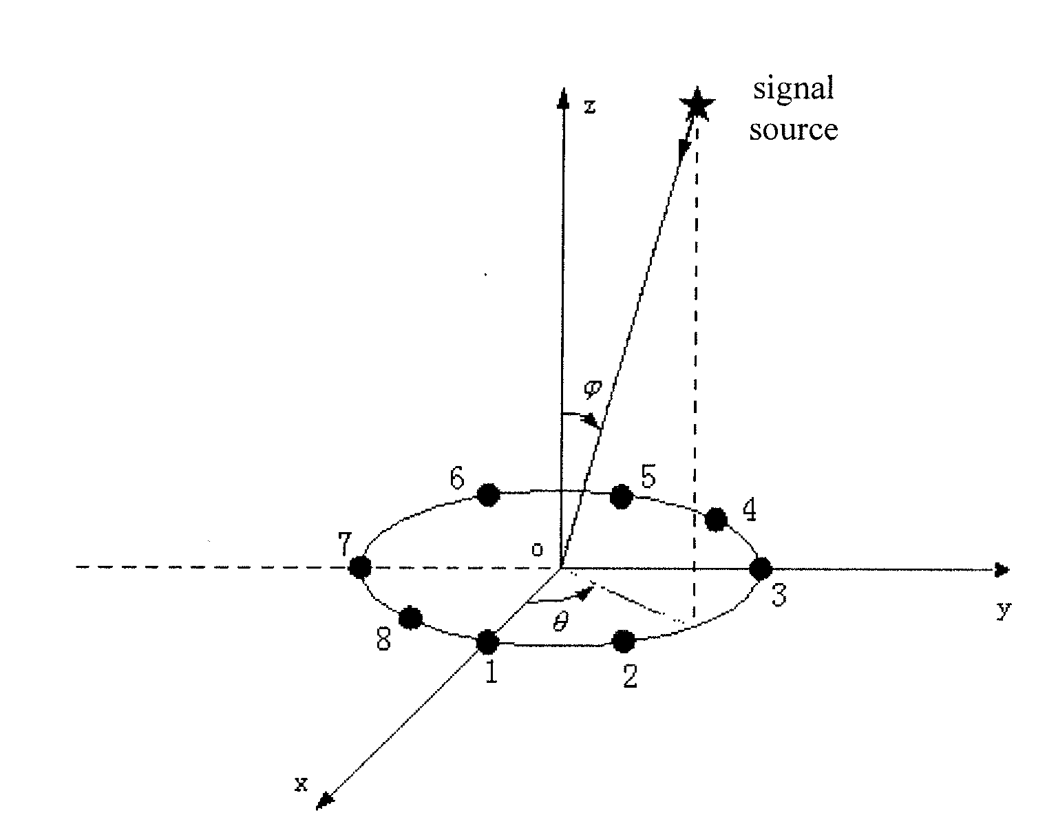
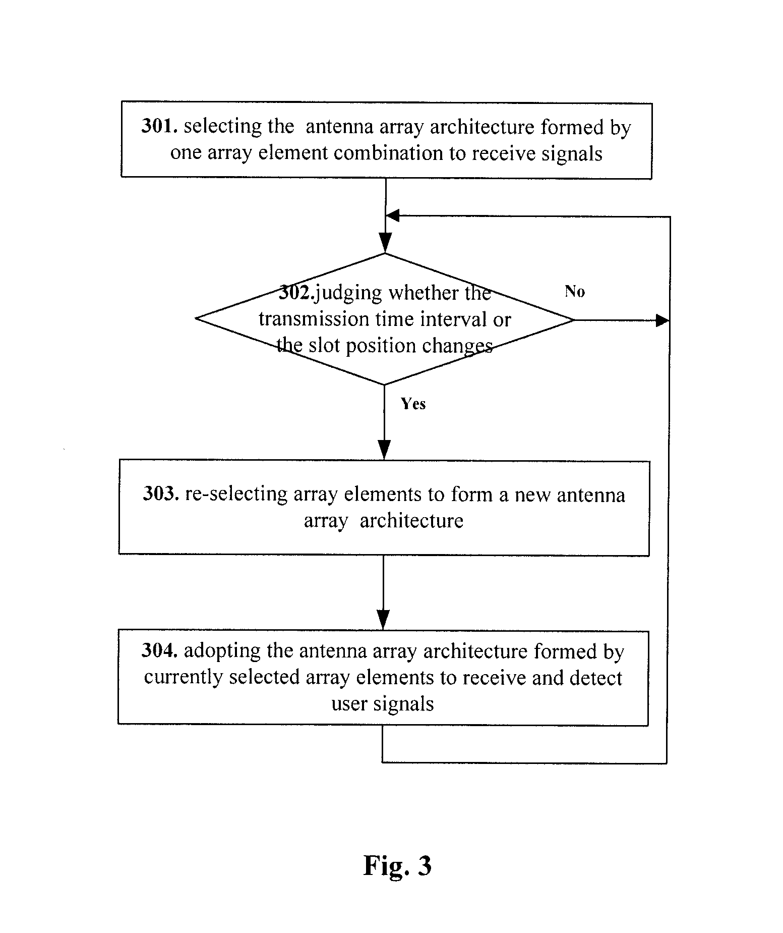
[0016]A main idea of the present invention is to select part array elements from all the array elements of the selected basic antenna array to form different antenna array architecture and to dynamically select different antenna array architecture according to changes of slot positions or the transmission time intervals (TTIs) to receive and detect user signals.

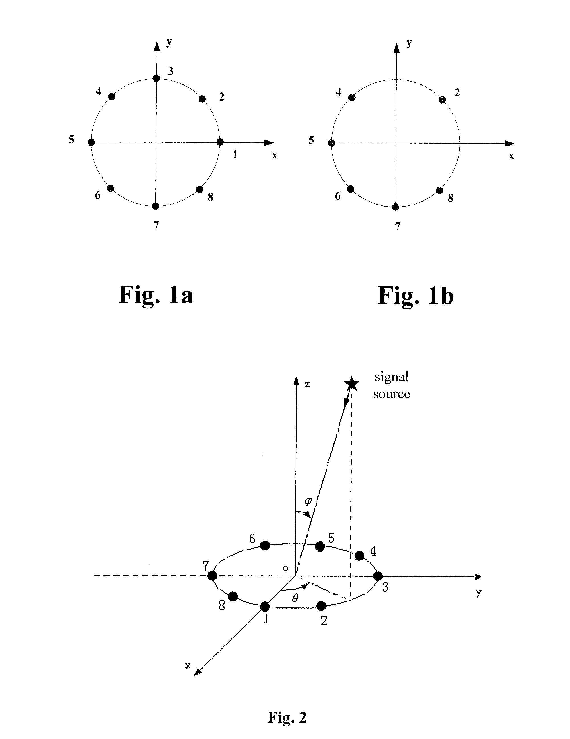
[0017]The existing antenna array is regarded as the basic antenna array and the existing antenna array refers to a linear antenna array or a circular antenna array of 4 array elements, 8 array elements or 16 array elements etc; the selecting of part array elements is to firstly determine the number of the array elements to be selected according to the system processing ability and / or the number of currently accessed users, then to determine array elements to be selected and it is random to select array elements, for example, if 4 array elements are to be selected from an 8-array element antenna array, 4 continuous array eleme...


PUM


Abstract

The present invention discloses a method for dynamically selecting antenna array architecture, deciding a basic antenna array, determining a number of required array elements, selecting determined number of array elements from all the array elements in the basic antenna array to form an antenna array architecture and receiving and detecting signals with the current antenna array architecture, the method further including: determining whether transmission time intervals and/or slot positions of received signals change, if so, re-selecting the determined number of array elements from all the array elements in the basic antenna array to form a new antenna array architecture and receiving and detecting signals with the new antenna array architecture, otherwise, continuing to determine. According to this method, not only the realization is simple but also that each array elements in the antenna array can receive arriving signals more reasonably so that the reliability of the antenna array to receive signals is improved.

Description

FIELD OF THE INVENTION[0001]The present invention relates to an antenna array technology, especially to a method for dynamically selecting antenna array architecture.BACKGROUND[0002]In the current Time Division Synchronous Code Division Multiple Access (TD-SCDMA) system, a base station generally uses an antenna array to receive and transmit user signals. The antenna array is composed by multiple antenna units according to a certain distribution mode so as to improve performance of the antenna system in mobile communications. Each antenna unit in the antenna array is an independent unit and each antenna unit is also called an array element and can be an omni-directional antenna or a directional antenna. The distribution of antenna units can be line type, ring type, plane type or three-dimension type. According to the antenna array technology, all the antenna units cooperate to perform receiving and transmission of user signals in different environment. Generally, the base station ado...

Claims


Application Information

Patent Timeline
IPC IPC(8): H01Q25/00H04B1/06H01Q21/29
CPCH01Q3/242H01Q21/205H04B7/02H04B7/08H04L1/02
Inventor XU, TIEZHULI, FENGKANG, SHAOLI
Owner SHANGHAI ULTIMATE POWER COMM TECH
Why Eureka
Try Eureka