Illumination device comprising a heat sink

Active Publication Date: 2009-05-21
OSRAM GMBH
View PDF11 Cites 5 Cited by
  • Summary
  • Abstract
  • Description
  • Claims
  • Application Information

AI Technical Summary

Benefits of technology

[0027]It is advantageous if the method for producing the illumination device comprises the following steps: in a first step, the cooling device is applied to the substrate plate and, in a second step, the cooling device is subdivided into regions which are electrically insulated from one another. Depending on the further boundary conditions during production, it is possible to carry out application of other elements to the substrate plate, in particular of the conductor tracks and the LEDs, before or after these steps. What i

Problems solved by technology

What is disadvantageous about an arrangement of this type, however, is the considerably impaired heat conduction—owing to the electrical

Method used


Image

  • Illumination device comprising a heat sink
  • Illumination device comprising a heat sink

Examples


Embodiment Construction

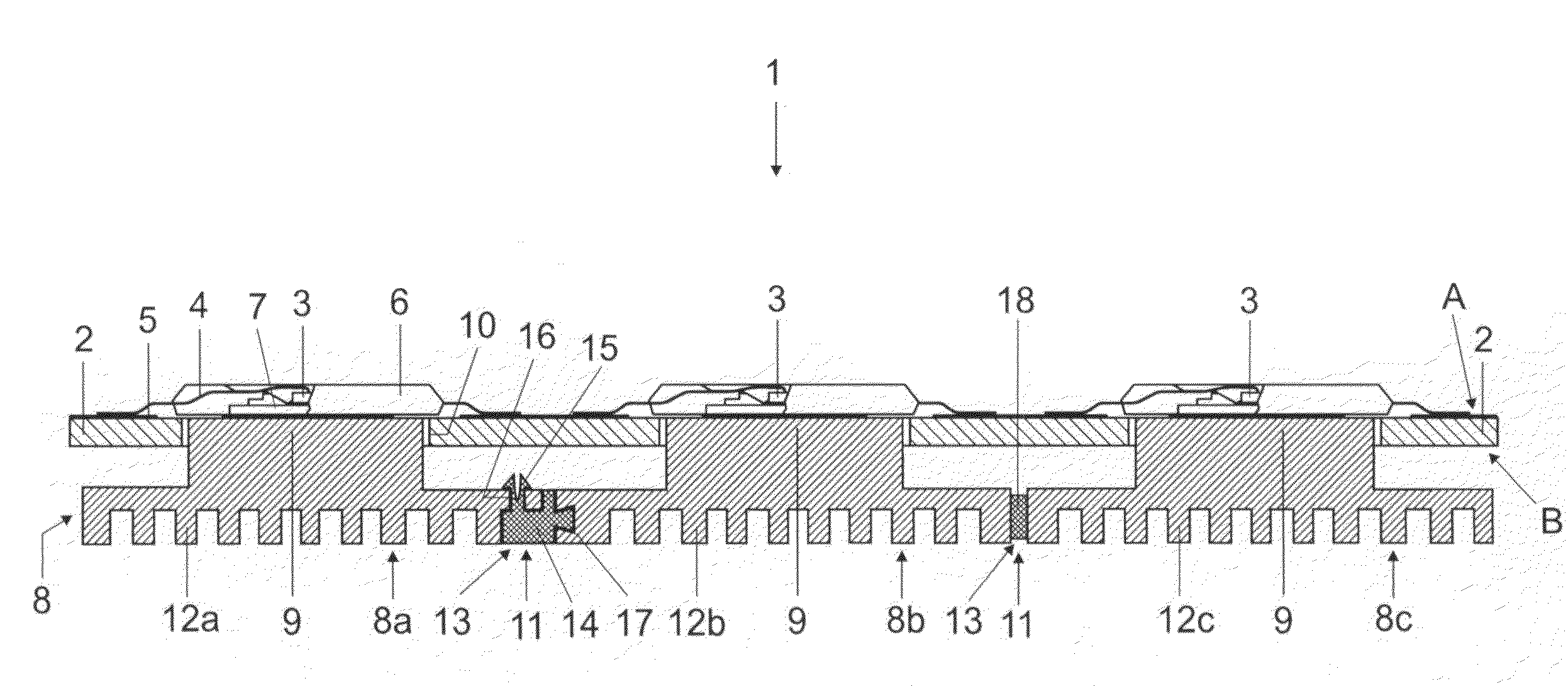
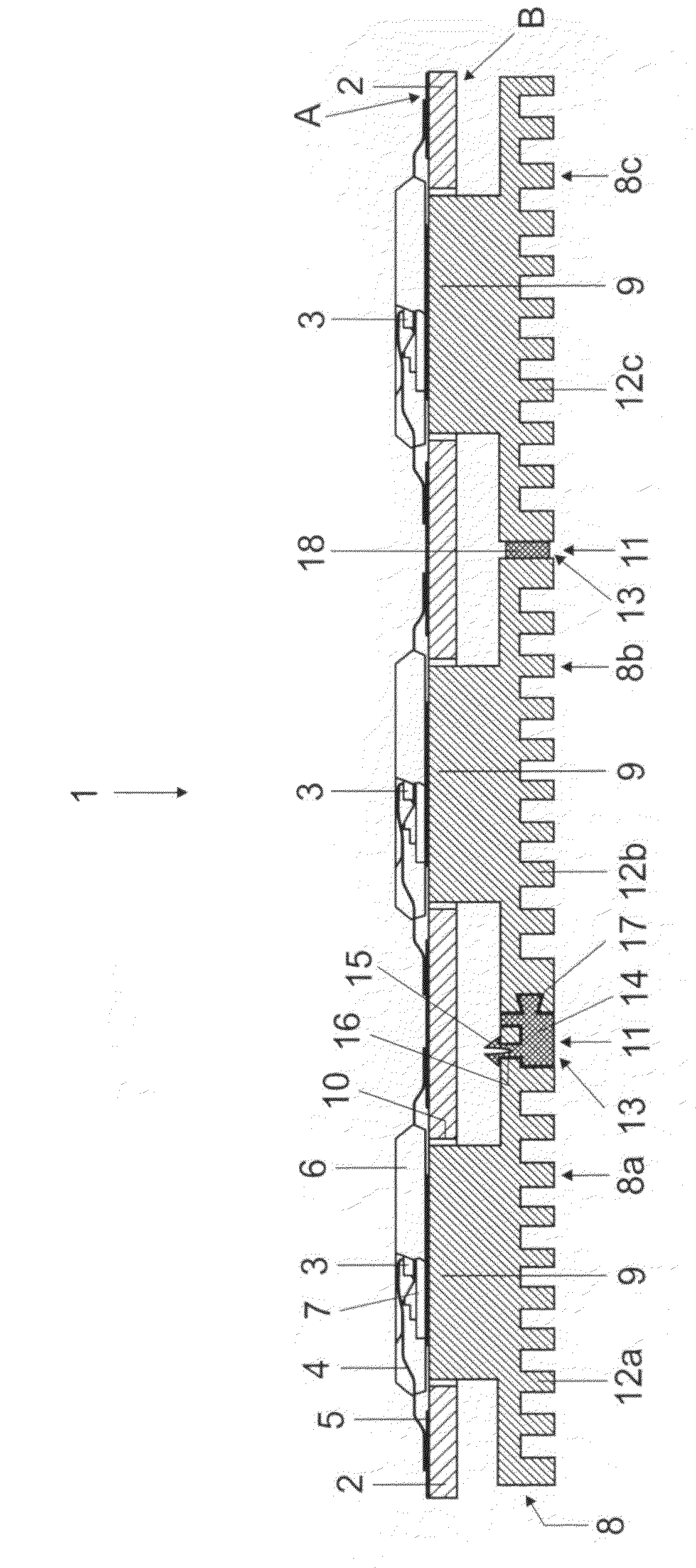
[0029]The illumination device 1 according to the invention essentially comprises a substrate plate 2, with three light emitting diodes 3 (LEDs) arranged on one side A (front side), thereof. Said diodes are known in many different embodiments which, in particular, in each case also emit electromagnetic radiation in different wavelengths ranging essentially from infrared through visible light to the ultraviolet region of the spectrum. The LEDs 3 are connected by means of power supply wires 4 to conductor tracks 5 likewise arranged on the front side A of the substrate plate 2. For protection against ambient influences, the LEDs 3 are each embedded into a housing 6. In order to dissipate the waste heat of the LEDs 3, the latter are in each case arranged on a so-called heat slug 7, which, on that side of the housing 6 which is assigned to the substrate plate 2, simultaneously serves as a termination of the housing 6. The heat slug 7 is accordingly produced from a material having good the...


PUM


Abstract

The invention relates to an illumination device (1) comprising at least one substrate plate (2), at least two light-emitting diodes (3) (LEDs) arranged on the same side (A) of the substrate plate (2), and at least one electrically conductive cooling device (8) arranged on the opposite side (B) of the substrate plate (2), in particular a metallic heat sink (8), wherein at least two LEDs (3) are thermally operatively connected to the cooling device (8) by means of in each case at least one thermal coupling device (9) formed from an electrically conductive material. According to the invention, the cooling device (8) has at least two regions (8a, 8b, 8c) which are electrically isolated from one another, wherein a first region (8b) is thermally and electrically operatively connected to at least one first LED (3), and a second region (8a, 8c) is thermally and electrically operatively connected to at least one second LED (3).

Description

TECHNICAL FIELD[0001]The invention relates to an illumination device comprising at least one substrate plate, at least two light-emitting diodes (LEDs) arranged on the same side of the substrate plate, and at least one electrically conductive cooling device arranged on the opposite side of the substrate plate, in particular a metallic heat sink, wherein at least two LEDs are thermally operatively connected to the cooling device by means of in each case at least one thermal coupling device formed from an electrically conductive material.PRIOR ART[0002]Illumination devices using light emitting diodes (LEDs) for generating light often have a substrate plate with one or a plurality of LEDs arranged on one side (front side) thereof. The LEDs are connected to one another or to an electronic control unit by means of conductive tracks.[0003]Modern high-power LEDs generate considerable amounts of heat in a very small space, and these amounts of heat have to be reliably dissipated in order th...

Claims


Application Information

Patent Timeline
IPC IPC(8): F21V29/00F21K99/00
CPCH05K1/0204H05K2201/10106H05K2201/09054H05K3/0061H01L2224/48091H01L2224/48247H01L2224/73265H01L2924/00014
Inventor KRAUS, ROBERT
Owner OSRAM GMBH
Why Eureka
Try Eureka