
Gas spring

Inactive Publication Date: 2006-08-24
STABILUS
View PDF8 Cites 6 Cited by
  • Summary
  • Abstract
  • Description
  • Claims
  • Application Information

AI Technical Summary

Benefits of technology

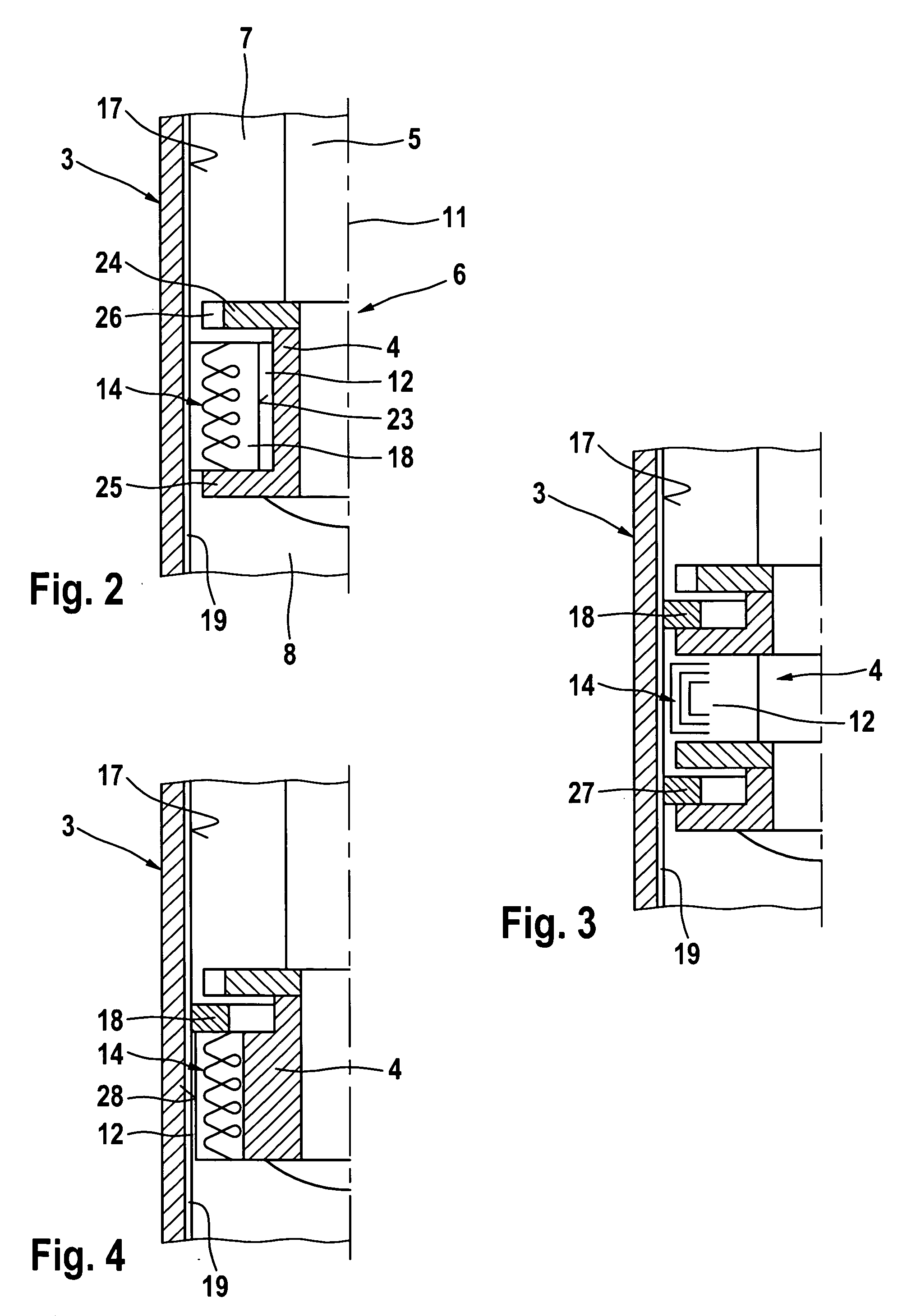
[0010] In a gas spring of the invention, this results in the special advantage that the pressure fluid, which is preferably a gas, such as, say, compressed nitrogen, is in direct contact with the heater as it flows. The heater is located directly in or immediately adjacent to a flow path of the pressure fluid. Compared to heaters known from the prior art, which heat a stationary gas volume, the invention provides significantly improved heat transfer from the heater to the pressure fluid, so that it becomes possible both to achieve faster heating of the pressure fluid and to reduce the required heating capacity. The efficiency of the heater is significantly enhanced. Due to heating of the pressure fluid as it flows through the flow channel, especially at low ambient temperatures, a pressure drop in the gas spring due to a temperature reduction can be compensated. Consequently, the gas spring of the invention is especially well suited for use within a wide temperature range, for example, in motor vehicles. The heater is preferably an electric heater, especially an electric resistance heater, which can be electrically connected, for example, by contact strips on the pressure tube and sliding contacts; it
[0024] In accordance with another advantageous refinement of the invention, in a middle section of the maximum travel of the actuating device, the inner wall of the pressure tube has a bypass groove, through which the pressure fluid can flow to bypass the actuating device. This groove, which serves as a bypass line, allows faster movement of the actuating device in its middle travel range, whereas the movement of the actuating device is slowed before the end-of-travel positions of the actuating device are reached due to increased opposing forces. In the case of a cylinder with a piston that has a piston rod, the groove thus extends over a certain middle section of the stroke of the piston but not into the end-of-travel regions of the stroke.

Problems solved by technology

In the gas springs described above, the heater acts on a compressed gas volume that is at rest, and this results in an inhomogeneous heat distribution in the compressed gas volume and a high heating capacity requirement.
Spring strut units of this type are heavy, are relatively expensive, and, in addition, produce unwanted noise.

Method used


Image

  • Gas spring
  • Gas spring
  • Gas spring

Examples


Embodiment Construction

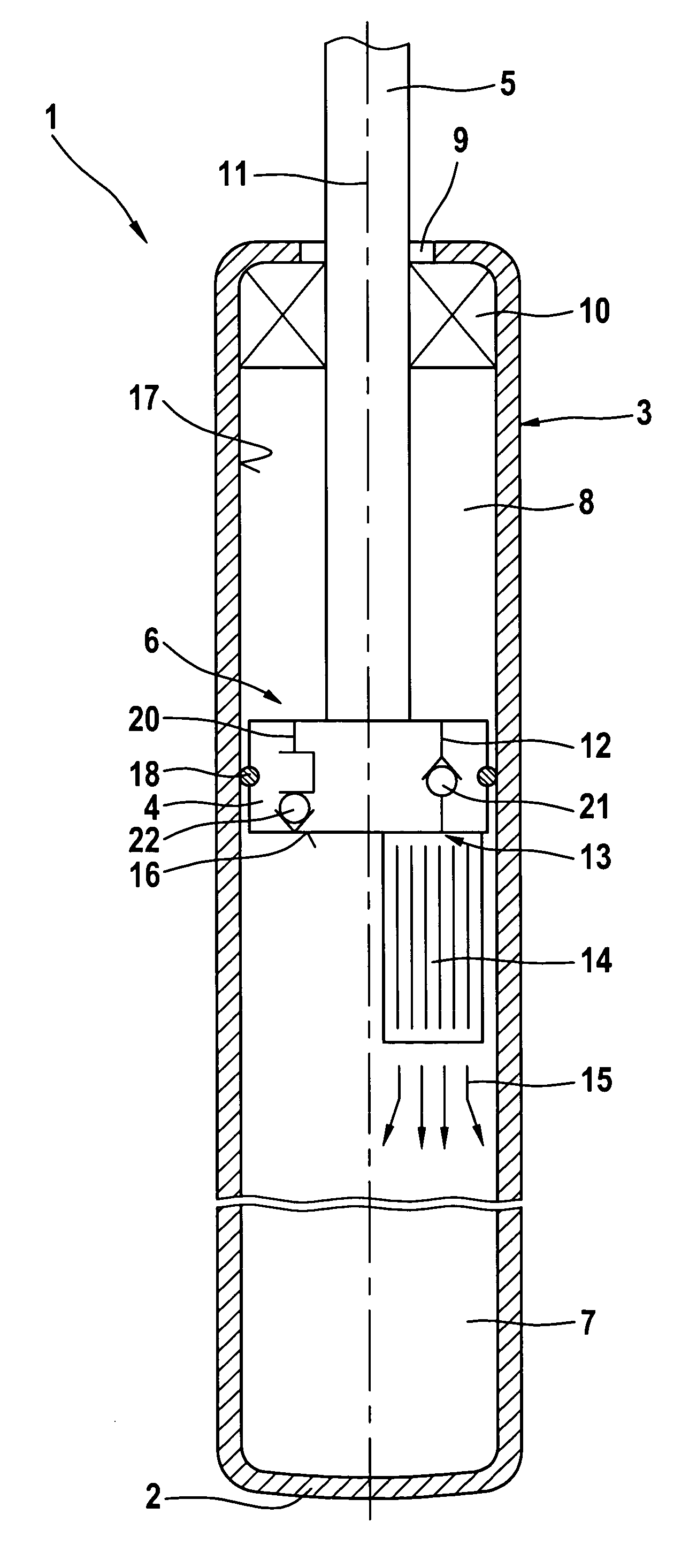
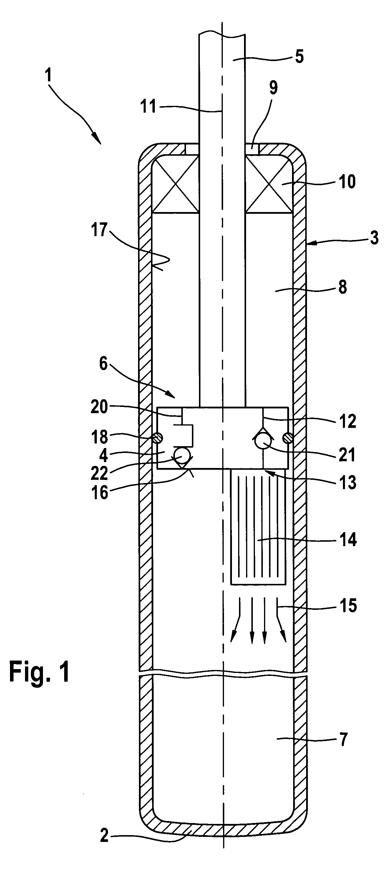
[0032]FIG. 1 shows a longitudinal section of a gas spring 1 with a pressure tube 3, which is closed at one end and has a base 2. The pressure tube 3 is filled with a gas that serves as the pressure fluid. A piston 4 with a one-sided piston rod 5 is guided in the pressure tube 3. This piston 4 serves as an actuating device 6, which can be moved relative to the pressure tube 3, namely, in the direction of the center axis 11 of the pressure tube 3, and which operates a motor vehicle tailgate (not shown) that is operatively connected with the piston rod 5. At the opposite end of the pressure tube 3 from the base 2, the pressure tube 3 has an opening 9, through which the piston rod 5 extends out of the pressure tube 3. A seal 10 seals the opening 9 from the piston rod 5.

[0033] The pressure tube 3 has a first pressure tube chamber 7 and a second pressure tube chamber 8, which are separated from each other by the piston 4. The two pressure tube chambers 7, 8 are connected by a flow channe...


PUM


Abstract

A gas spring includes a pressure tube having a first pressure chamber and a second pressure chamber, the pressure tube being filled with a pressure fluid. An actuating device that can move relative to the pressure tube is acted on by the pressure fluid. A flow channel connects the first pressure chamber to the second pressure chamber, and a heater is arranged within the flow channel and / or immediately adjacent to the flow channel.

Description

BACKGROUND OF THE INVENTION [0001] 1. Field of the Invention [0002] The invention concerns a gas spring with a pressure tube that has a first pressure tube chamber and a second pressure tube chamber and is filled with a pressure fluid, with a pressure fluid flow channel that connects the first pressure tube chamber and the second pressure tube chamber, and with a heater for heating the pressure fluid, wherein the pressure fluid can act on an actuating device that moves relative to the pressure tube. [0003] 2. Description of the Related Art [0004] A previously known gas spring of this type is designed as a lifting aid for opening and holding open tailgates and trunk lids of motor vehicles. This gas spring has a metallic cylinder that is closed at one end, a damping piston supported therein, a metallic piston rod connected to the damping piston, and a seal at the open end of the cylinder between the cylinder and the piston rod. In general, the extension force of gas springs is tempera...

Claims


Application Information

Patent Timeline
IPC IPC(8): F16F9/52
CPCF16F9/0218F16F9/52F16F2222/02
Inventor MINTGEN, ROLF
Owner STABILUS
Learn More