Plant for assembling mechanical parts on vehicle bodies

Active Publication Date: 2015-02-19
CPM
View PDF33 Cites 3 Cited by
  • Summary
  • Abstract
  • Description
  • Claims
  • Application Information

AI Technical Summary

Benefits of technology

The invention aims to create an assembly plant that is easy to set up, trustworthy and can handle body handling operations between pallets without the need for manual adjustment. The conveyor uses balance supports to absorb any stress caused by assembly operations, resulting in savings in time and space. Overall, the invention simplifies the assembly process and makes it more efficient.

Problems solved by technology

Furthermore, the body can be subjected to undesired mechanical stress during assembly operations.

Method used


Image

  • Plant for assembling mechanical parts on vehicle bodies
  • Plant for assembling mechanical parts on vehicle bodies
  • Plant for assembling mechanical parts on vehicle bodies

Examples


Embodiment Construction

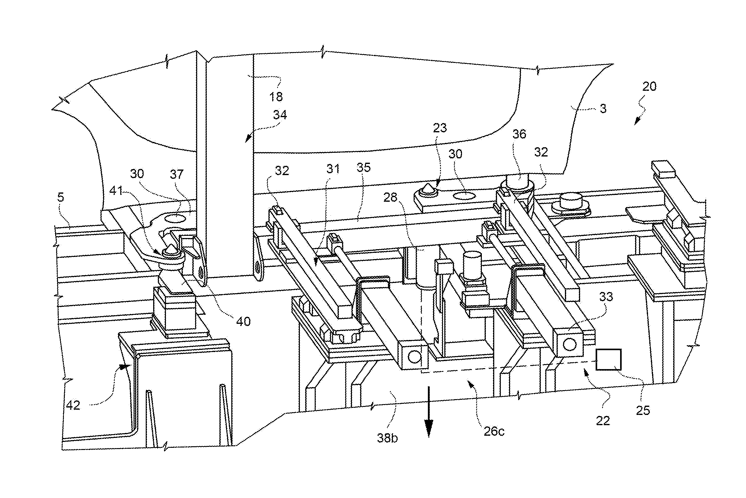
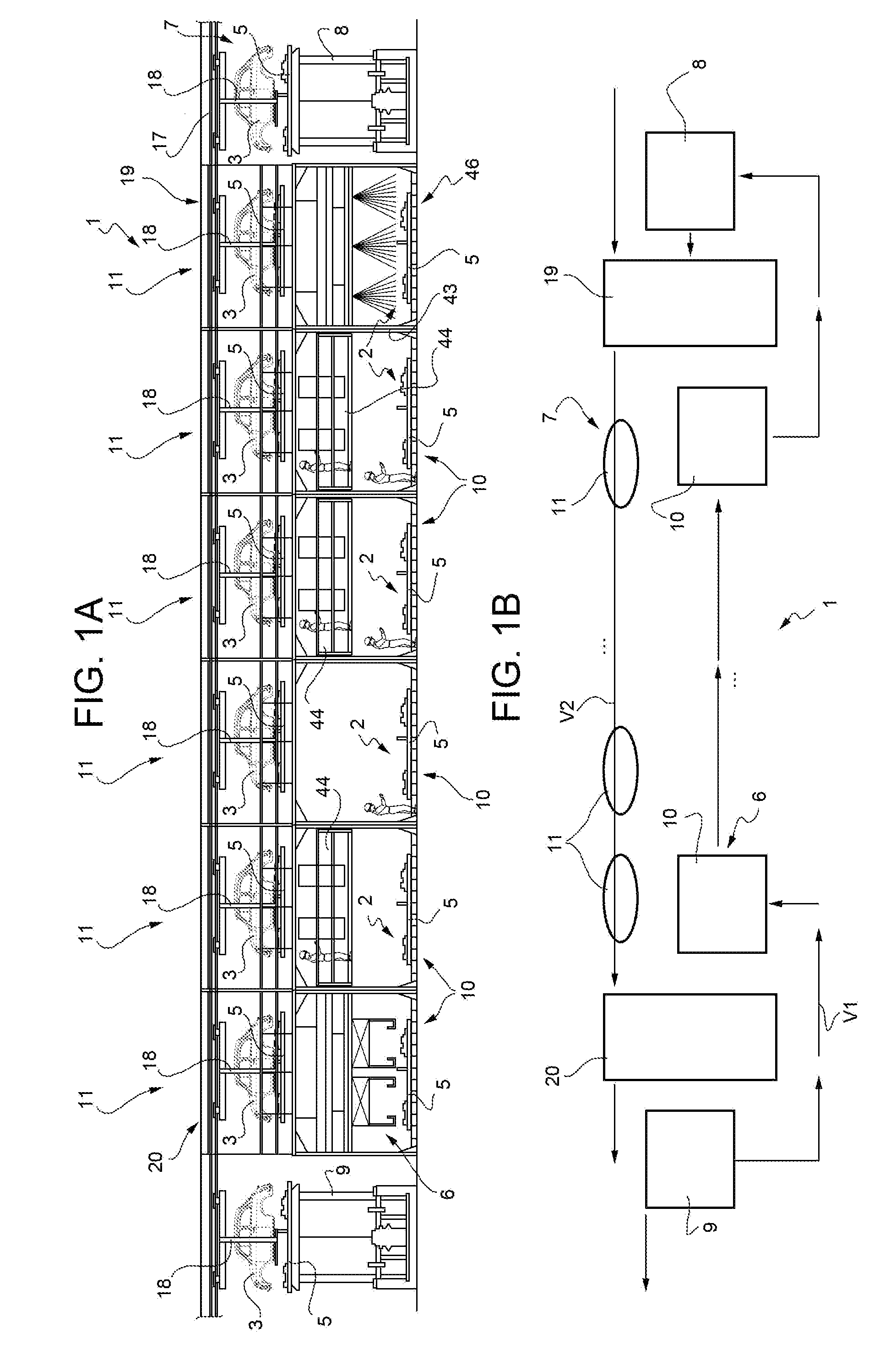
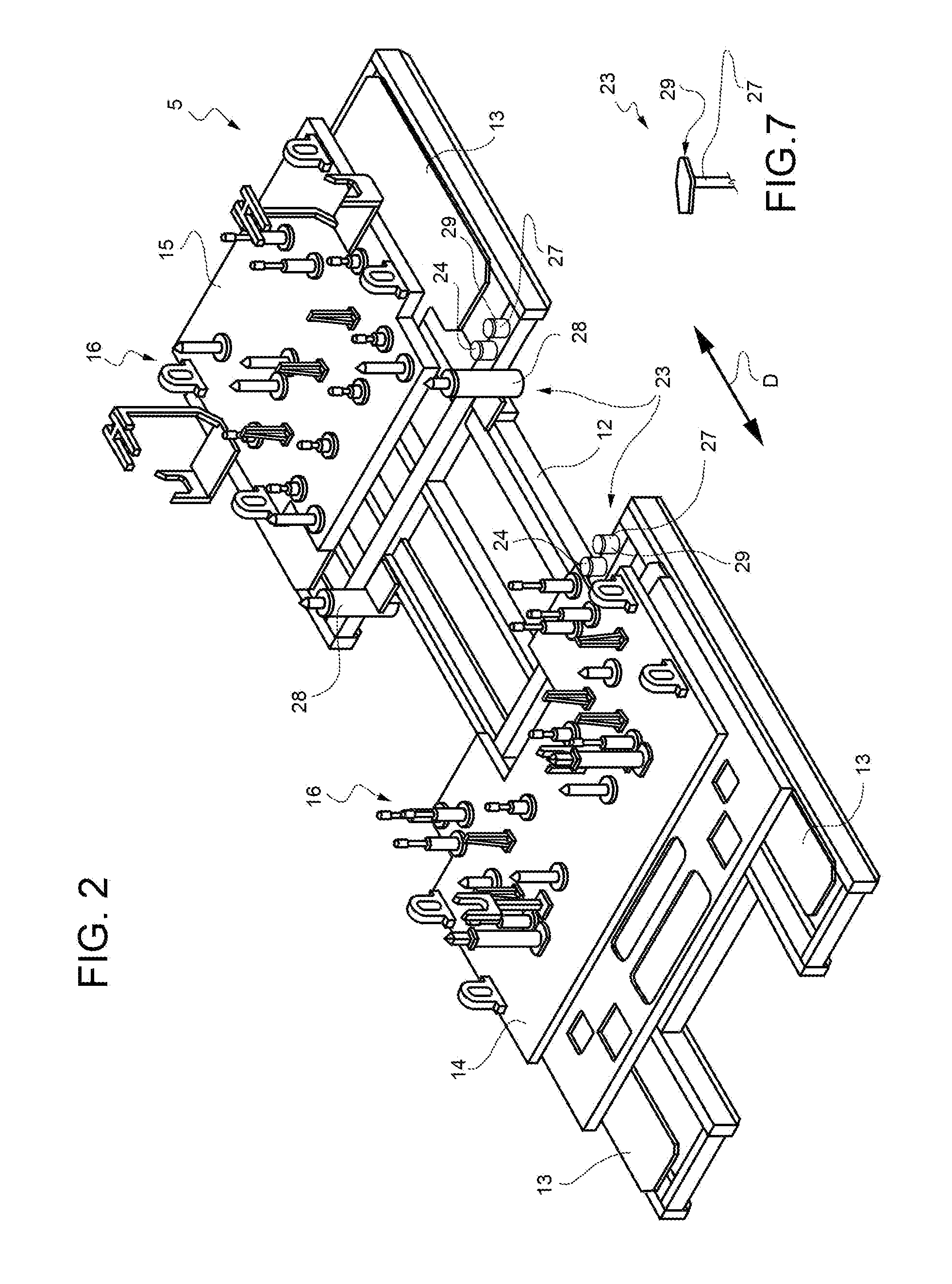
[0021]With reference to FIGS. 1 to 7, reference numeral 1 indicate, as a whole, a plant for assembling mechanical parts 2, known and only illustrated schematically for simplicity, on vehicle bodies 3; the plant 1 comprises an assembly line 4 along which a plurality of pallets 5 are circulated in a closed loop; the line 4, on the whole of known type, thus constitutes an endless loop conveyor line for the pallets 5 along the aforementioned closed loop that, in the preferred embodiment, is arranged parallel to a vertical plane defined by the plane of the sheet in FIG. 1A.

[0022]The line 4 is divided into a first section 6 and into a second section 7, which is arranged over the first section 6 in the preferred embodiment shown; sections 6 and 7 have the same extension in the direction of movement of the pallets 5, which is straight in the example shown, and a lifting station 8 and a lowering station 9, both of known type, are arranged at the beginning and end of the first section 6 for t...


PUM


Abstract

A plant including: an assembly line along which a plurality of pallets are circulated in a closed loop, divided into a first section, where the pallets are loaded in a plurality of first stations with mechanical parts to be assembled, and into a second section, where the pallets advance along a plurality of second stations; a conveyor arranged at least partially parallel to and above the second section, along which a plurality of balance supports provided with bodies run; a coupling station, arranged immediately upstream of the second section, where the pallets are integrally coupled to the balance supports; and a decoupling station, where the pallets are separated from the balance supports; each pallet having selectively engageable and releasable fastening means for a balance support and elastic means able to receive the balance support resting thereon.

Description

TECHNICAL FIELD[0001]The present invention relates to a plant intended to carry out the assembly of mechanical parts on vehicle bodies.[0002]Hereinafter, “mechanical parts” means both the engine of the vehicle and / or mechanical parts of the transmission (gearbox, axles, etc.), and any other mechanical part destined to be assembled on a vehicle body / bodywork, such as the front and rear suspension, also including the associated springs and shock absorbers.BACKGROUND ART A plant of this type is known from EP2340982, comprising an assembly line divided into two sections, which are mounted one above the other, the first beneath the second. A plurality of pallets, on which the mechanical parts to be assembled on each body are arranged in sequence and according to a pre-established layout, are moved along the first section in a first determined direction. The completed pallets are then moved to the second section by an elevator, and here they are moved in a second direction, opposite to th...

Claims


Application Information

Patent Timeline
IPC IPC(8): B62D65/18B23P19/04B23P21/00
CPCB62D65/18B23P19/04B23P21/004B62D65/022Y10T29/49829Y10T29/534Y10T29/53417Y10T29/53539Y10T29/53548
Inventor BELLEZZA, MASSIMO
Owner CPM
Why Eureka
Try Eureka