Universal Serial Bus (USB) Flash Drive with Swivel Cap Functionalities with Two Locking Positions

a technology of universal serial bus and flash drive, which is applied in the direction of electrical apparatus casing/cabinet/drawer, coupling device connection, instruments, etc., can solve the problems of loss or misplacement of the cover, adversely affecting the security of the connector,

Inactive Publication Date: 2008-11-13
SUPER TALENT TECH CORP
View PDF5 Cites 37 Cited by
  • Summary
  • Abstract
  • Description
  • Claims
  • Application Information

AI Technical Summary

Benefits of technology

[0007]Briefly, an embodiment of the present invention includes a slim USB device having an end used to couple the USB flash drive to a host, an opposite end, and a swivel “strap shaped” metal cap having a circle cut out disposed on both cap legs. The snap coupling circle attachment allows the swivel cap to rotate substantially into a first and a second locking position and to rotate substantially 360 degrees about the z-axis of the USB device. The metal cap is generally in a locked position when the snap slot is aligned atop the snap lock tab such that the protrusion snap r

Problems solved by technology

There is therefore the possibility of losing or misplacing the cover because it is completely detached when removed from the USB plug connector.
Further

Method used


Image

  • Universal Serial Bus (USB) Flash Drive with Swivel Cap Functionalities with Two Locking Positions
  • Universal Serial Bus (USB) Flash Drive with Swivel Cap Functionalities with Two Locking Positions
  • Universal Serial Bus (USB) Flash Drive with Swivel Cap Functionalities with Two Locking Positions

Examples


Embodiment Construction

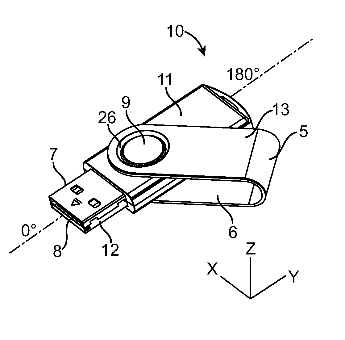
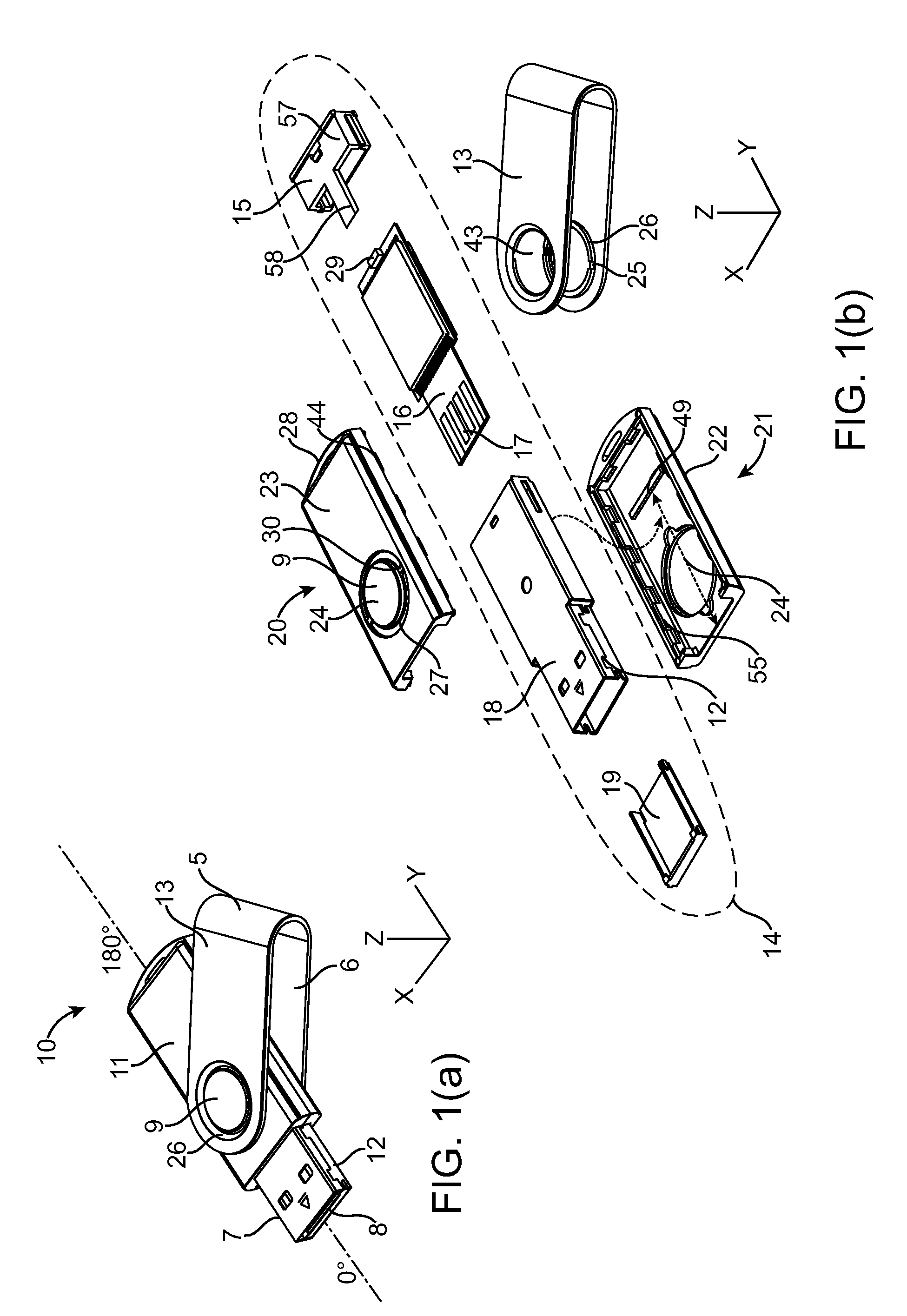
[0033]Referring now to FIG. 1(a), a universal serial bus (USB) flash drive 10 is shown to include USB metal plug 12, USB device 11, snap coupling circle attachment 9, and a swivel “strap-shaped” metal cap 13, in accordance with an embodiment of the present invention. FIG. 1(a) shows an angular perspective of the top side of the USB flash drive 10 shown at an angle so as to only show two of the four sides thereof.

[0034]USB metal plug 12 extends out from USB device 11 and is generally shown to be rectangular in shape including metal plug sides 7. USB device 11 is shown to partially enclose the metal plug 12. The metal plug 12 is shown to be narrower in width than the width of the USB device 11. The USB metal plug 12 is shown to include a metal plug front face 8 that is a hollow front side of plug 12. The metal plug sides 7 are each located on the lateral sides of plug 12 and are also partially encapsulated by the USB device 11.

[0035]The metal plug 12 generally serves to interface the ...


PUM


Abstract

A Universal Serial Bus (USB) flash drive includes a slim USB device having an end used to couple the USB flash drive to a host and an opposite end, and a swivel “strap shaped” metal cap having a circle cut out disposed on both cap legs. The snap coupling circle attachment allows the swivel cap to rotate substantially into a first and a second locking position and to rotate substantially 360 degrees about the z-axis of the USB device. The metal cap is generally in a locked position when the snap slot is aligned atop the snap lock tabs such that the protrusion snap ring is descended downward until the positioned flush against the snap lock groove. When unlocked the protrusion snap ring is raised up and rested upon the two snap lock tabs.

Description

CROSS REFERENCE TO RELATED APPLICATIONS[0001]This application is a continuation-in-part (CIP) of co-pending U.S. patent application for “A Method for Manufacturing a Memory Device”, U.S. application Ser. No. 10 / 991,313, filed Nov. 16, 2004. This application is also a continuation in part of U.S. patent application for “USB Device with Integrated USB Plug with USB Substrate Supporter Inside”, U.S. application Ser. No. 11 / 309,847, filed Oct. 12, 2006. This application is also a continuation in part of U.S. patent application for “Flash Memory Controller for Electronic Data Flash Card”, U.S. application Ser. No. 11 / 466,759, filed on Aug. 23, 2006, which is a CIP of “System and Method for Controlling Flash Memory”, U.S. application Ser. No. 10 / 789,333, filed on Feb. 26, 2004.BACKGROUND OF THE INVENTION[0002]1. Field of the Invention[0003]The present invention relates generally to the field of universal serial bus (USB) flash drives (or devices) and particularly to USB flash drives havin...

Claims


Application Information

Patent Timeline
IPC IPC(8): G06F1/16H01S4/00
CPCG06K19/07732H01R13/447Y10T29/49002H05K5/0278H01R13/504
Inventor NGUYEN, DAVIDNI, JIM CHIN-NANLEE, CHARLES CHUNGMA, ABRAHAM CHIH-KANG
Owner SUPER TALENT TECH CORP
Why Eureka
Try Eureka