Method and apparatus for electronically controlling a motorized device

a motorized device and electronic control technology, applied in the field of microprocessing devices, can solve the problems of inability to control the wheelchair, requiring contact with the body, and requiring relatively complicated circuits, and users of power wheelchairs often times do not have a great amount of control over their head (or other body parts) for controlling the wheelchair

Inactive Publication Date: 2008-11-27
ASHMORE C RUCKER +1
View PDF11 Cites 15 Cited by
  • Summary
  • Abstract
  • Description
  • Claims
  • Application Information

AI Technical Summary

Problems solved by technology

One drawback of sensing circuits used for these types of wheelchair controls is that contact with the body is required.
However, the sensing circuit incorporates proportional signals from sensors for controlling both forward/reverse movements and left/right turns of the wheelchair and, furthermore, requires relatively complicated circuitry.
Users of power wheelcha

Method used


Image

  • Method and apparatus for electronically controlling a motorized device
  • Method and apparatus for electronically controlling a motorized device
  • Method and apparatus for electronically controlling a motorized device

Examples


Embodiment Construction

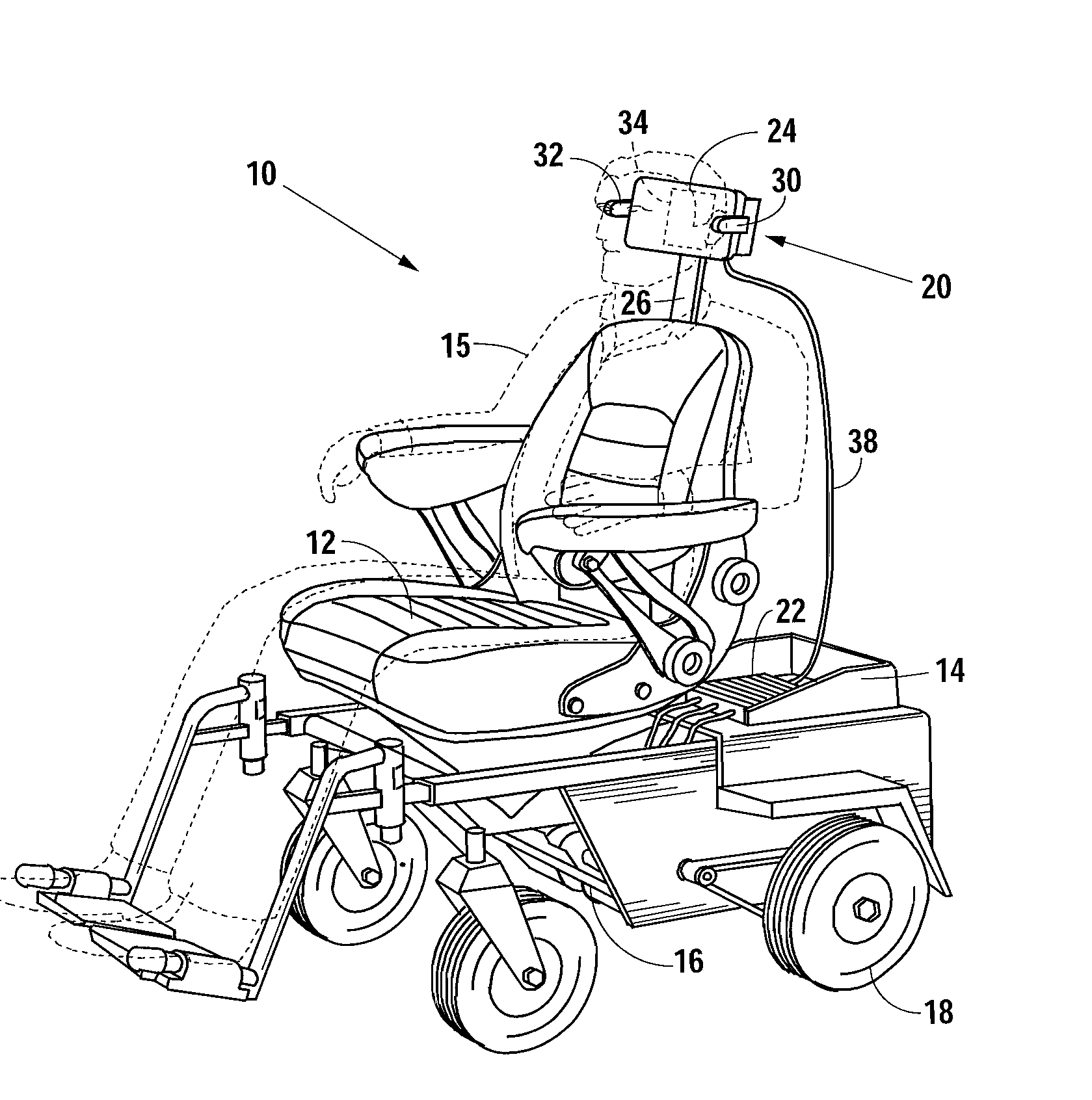
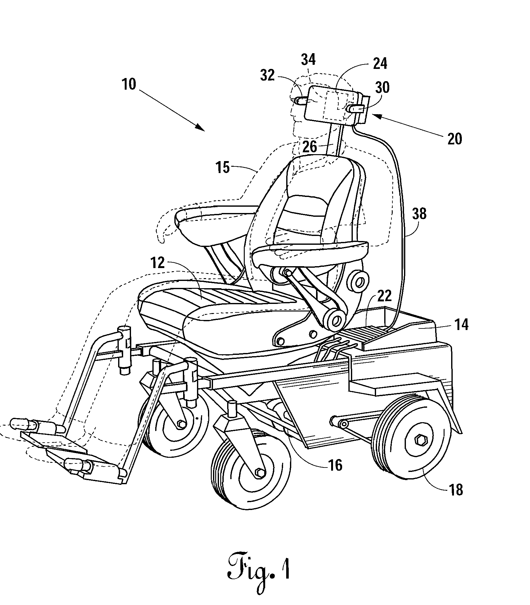
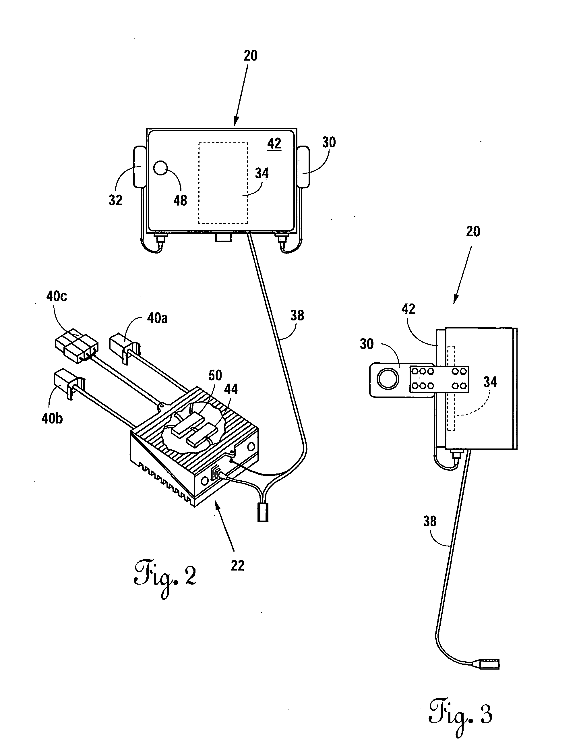
[0025]With reference to FIG. 1, a motorized device 10 (e.g., a vehicle such as a wheelchair) according to the present invention includes a seat portion 12, which accommodates a user (e.g., a passenger) 15, a housing 14, which accommodates at least one motor 16 for moving the device 10, rear wheels 18, a sensor module 20, and a control module 22. The wheels 18 are mechanically connected to the motor 16 in a conventional manner such that the device 10 moves when the motor 16 causes the rear wheels 18 to turn. In FIG. 1 only the left rear wheel 18 is shown. However, it can be appreciated that an identical right rear wheel (not shown) is mounted opposite the left rear wheel 18. The control module 22 is electrically connected to the motor 16 such that control signals, which cause the motor 16 to turn the wheels 18 at respective speeds, are received in the motor 16 from the control module 22. The sensor module 20 electrically communicates with the control module 22. Sensor signals transmi...


PUM


Abstract

An electronic controller for a motorized device includes a signal generator generating an output signal to the motorized device. A non-proportional proximity sensor communicates with the signal generator. A proportional proximity sensor communicates with the signal generator. The output signal is determined as a function of respective signals communicated from the proximity sensors to the signal generator. A direction and speed of the motorized device is determined as a function of the output signal.

Description

CROSS REFERENCE TO RELATED APPLICATIONS[0001]This application is a continuation-in-part of U.S. patent application Ser. No. 10 / 273,320, filed Oct. 17, 2002, which claims benefit of U.S. Provisional Application No. 60 / 343,872, filed Oct. 19, 2001.STATEMENT REGARDING FEDERALLY SPONSORED RESEARCH & DEVELOPMENT[0002]This invention was not made by an agency of the United States Government nor under contract with an agency of the United States Government.BACKGROUND OF THE INVENTION[0003]The present invention relates to a microprocessing device used in conjunction with capacitive elements for sensing a position of an object and producing an output signal as a function of the position. It finds particular application in conjunction with controlling the operation of a motorized wheelchair and will be described with particular reference thereto. It will be appreciated, however, that the invention is also amenable to other like applications.[0004]A Wheelchair enables a disabled person, whose a...

Claims


Application Information

Patent Timeline
IPC IPC(8): G05D3/00
CPCA61F4/00A61G5/045A61G2203/14G06F3/012
Inventor ASHMORE, C. RUCKERPHAM, TOAN D.
Owner ASHMORE C RUCKER
Why Eureka
Try Eureka