
Air bag device for automobile

a technology for air bags and automobiles, which is applied in the direction of vehicle components, pedestrian/occupant safety arrangements, vehicular safety arrangments, etc., can solve the problems of not taking into consideration the interference between the head protection air bag member and and not taking into consideration the side air bag member

Inactive Publication Date: 2008-12-04
TOYOTA JIDOSHA KK
View PDF5 Cites 16 Cited by
  • Summary
  • Abstract
  • Description
  • Claims
  • Application Information

AI Technical Summary

Benefits of technology

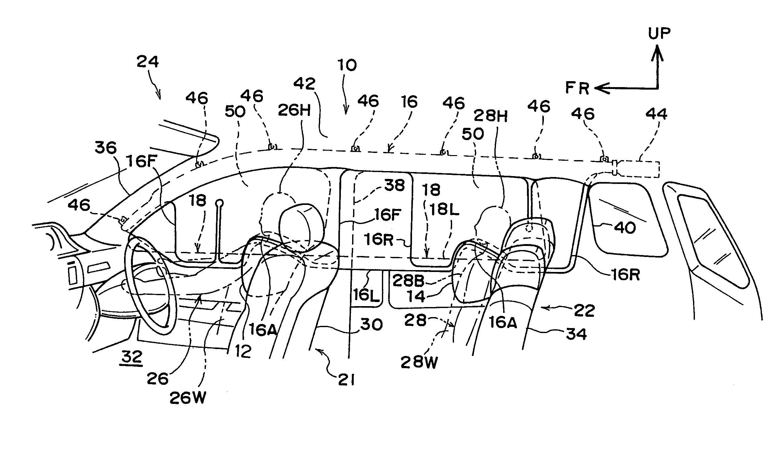
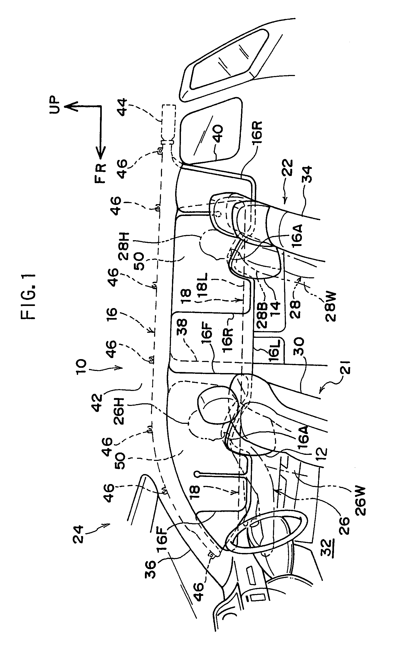
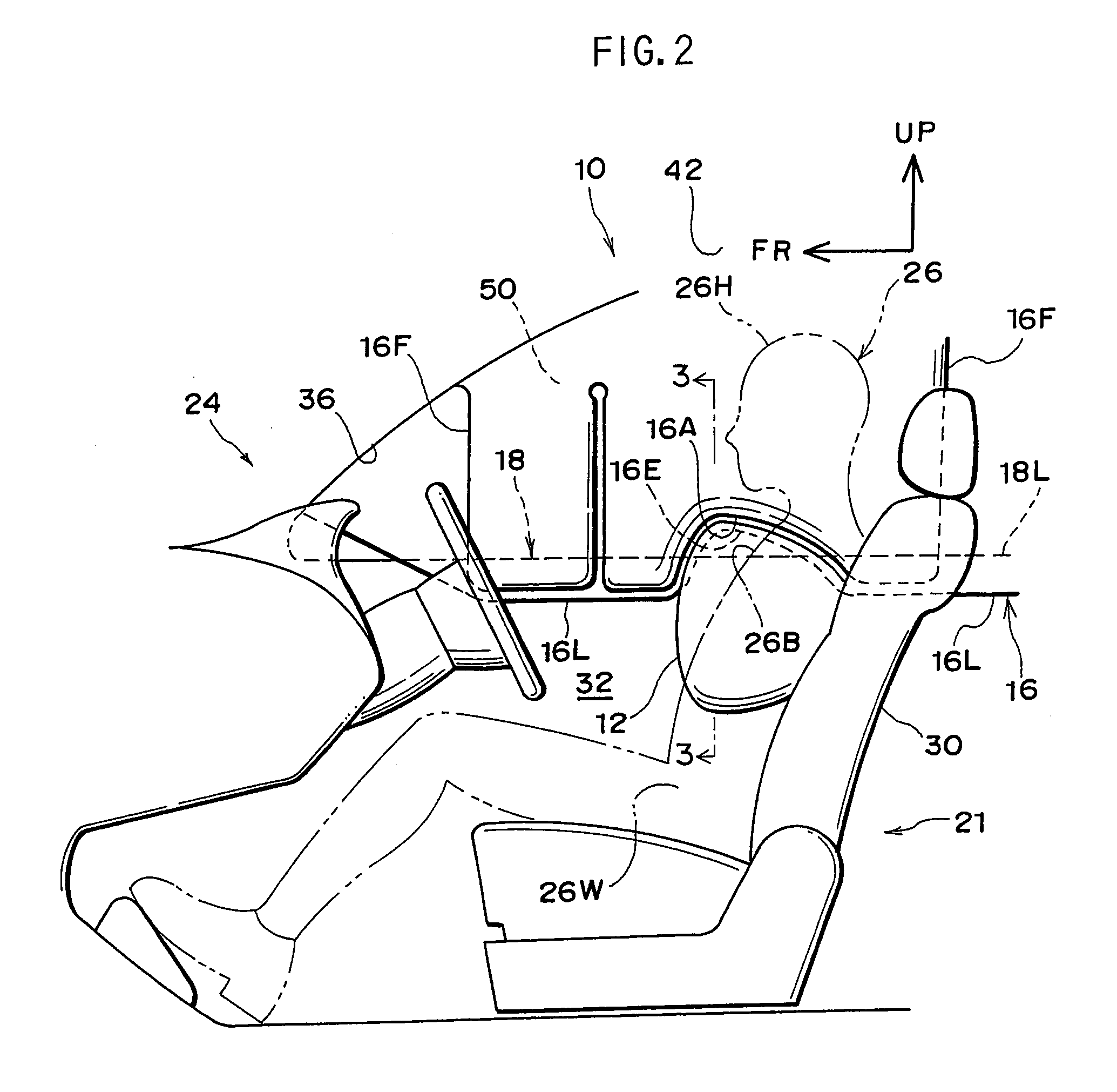
[0009]According to the first mode of the invention, when the side impact or the rolling over of the vehicle is brought about, the side air bag member deploys between the passenger seated on the vehicle seat and the vehicle body head portion, and the head portion protection air bag member deploys in the curtain shape in the downward direction inside of the vehicle compartment up to the position of overlapping the head portion protection air bag member and the deploying region of the side air bag member in the vehicle width direction. At this occasion, the deployed side air bag member can be fitted to the head portion protection air bag member. Therefore, an interference between the side air bag member and the head portion protection air bag member can be restrained while deploying the head portion protection air bag member to the position of overlapping the deploying region of the side air bag member in the vehicle width direction, thereby, both of side impact and the rolling over of the vehicle can be dealt with.

Problems solved by technology

However, according to a related art described in Japanese Patent No.3520836, the head protection air bag member is not extended to the position lower than the belt line of the door, and interference between the head protection air bag member and the side air bag member is not taken into consideration at all.
Further, according to the related art described in Japanese Patent No.3520836 mentioned above, a combination of the air bag expanded to deploy in the curtain shape and the side air bag member is not taken into consideration at all.

Method used


Image

  • Air bag device for automobile
  • Air bag device for automobile
  • Air bag device for automobile

Examples


first embodiment

[0017]In FIG. 1, an air bag device for automobile 10 according to the embodiment includes side air bag member 12 and 14 and a head protection air bag member 16.

[0018]The side air bag member 12 is a bag member arranged in a folded state inside of a door 18 constituting a side portion of a vehicle body or at a front vehicle seat 21 constituting an example of a vehicle seat and expands by being supplied with a gas from an inflator, not illustrated, and deployed between a passenger 26 seated on the front vehicle seat 21 and the door 18 in side impact or in rolling over of a vehicle 24.

[0019]According to the embodiment, an air bag module (not illustrated) constituted by containing, for example, the side air bag member 12 and an inflator inside of an air bag case is inwardly provided at a side portion on a side of the door of the seat back 30 of the front vehicle seat 21. The inflator is constituted to be operated by receiving an operating current from an air bag ECU, not illustrated, for...

second embodiment

[0042]In FIG. 4 through FIG. 6, in an air bag device for automobile 20 according to the embodiment, the recessed portion 16A of the head portion protection air bag member 16 is set to be larger than that of the first embodiment in a front and rear direction of the vehicle in consideration of a case in which the front vehicle seat 21 is constituted to be slidable in the front and rear direction of the vehicle and a position of the front vehicle seat 21 in the front and rear direction is constituted to be able to adjust in a predetermined range.

[0043]As shown by FIG. 5, a front wall portion 16B of the recessed portion 16A of the head portion protection air bag member 16 upon deployment is formed to rise from, for example, the lower edge portion 16L in a rear direction and in a skewed upper direction of the vehicle in correspondence with a contour of the front portion of the side air bag member 12 in a side view of the vehicle and continues to an upper wall portion 16G of the recessed ...


PUM


Abstract

An air bag device for automobile comprising a side air bag member arranged at a vehicle body side portion or a vehicle seat in a folded state, expanded by being supplied with a gas upon a vehicle being impacted from the side or rolling over, and which deploys between a passenger seated on the vehicle seat and the vehicle body side portion, and a head portion protection air bag member which deploys in a curtain shape in a downward direction inside of a vehicle compartment up to a position of overlapping a deploying region of the side air bag member in a vehicle width direction, and which has a shape that fits with the deployed side air bag member.

Description

CROSS-REFERENCE TO RELATED APPLICATIONS[0001]This application claims priority under 35USC 119 from Japanese Patent Application, insert identifying information for all JP priority application No.2007-136823, the disclosure of which is incorporated by reference herein.BACKGROUND OF THE INVENTION[0002]1. Field of the Invention[0003]The present invention relates to an air bag device for automobile, particularly relates to an air bag device for automobile in consideration of side impact and rolling over of a vehicle.[0004]2. Description of the Related Art[0005]JP-A No.2000-190807 discloses a constitution of combining a head protection air bag member and a side air bag member as an apparatus of expanding a vehicle passenger binding system. Further, Japanese Patent No.3520836 discloses a constitution in which an air bag expanded to deploy in a curtain shape at a side portion in a vehicle compartment includes a head protection expansion area constituted substantially by an upper half thereo...

Claims


Application Information

Patent Timeline
Patent Type & Authority Applications(United States)
IPC IPC(8): B60R21/16B60R21/207B60R21/20B60R21/21B60R21/213B60R21/232
CPCB60R21/23138B60R21/232B60R2021/23107
Inventor IDEUE, MASAHIRO
Owner TOYOTA JIDOSHA KK
Learn More