
Stabilising Means

a technology of stabilising means and rotors, which is applied in the direction of mechanical equipment, instruments, transportation and packaging, etc., can solve the problems of limiting the speed of the rotor and hence the weight of the rotor

Active Publication Date: 2008-12-11
VEEM
View PDF41 Cites 8 Cited by
  • Summary
  • Abstract
  • Description
  • Claims
  • Application Information

AI Technical Summary

Benefits of technology

[0028]The invention will be more fully understood in the light

Problems solved by technology

Gyroscopic stabilising systems have been proposed in the past but because of their mass and the space required to accommodate them they have generally been limited to use with large vessels.
It is the axial load that limits the speed of the rotor and hence the weight of rotor required.

Method used


Image

  • Stabilising Means
  • Stabilising Means
  • Stabilising Means

Examples


Embodiment Construction

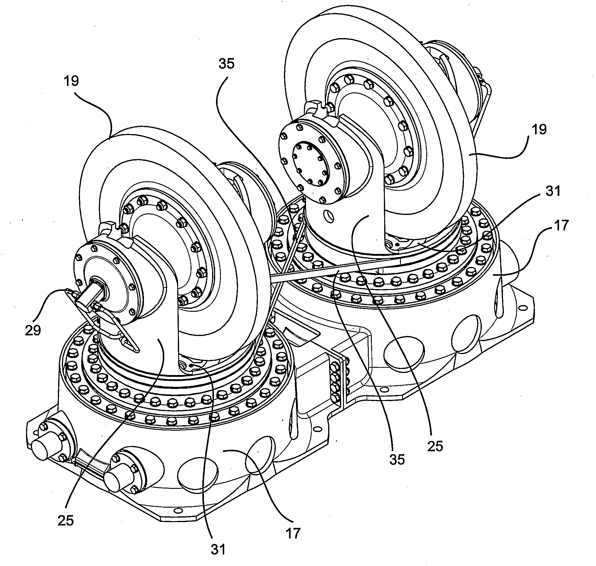
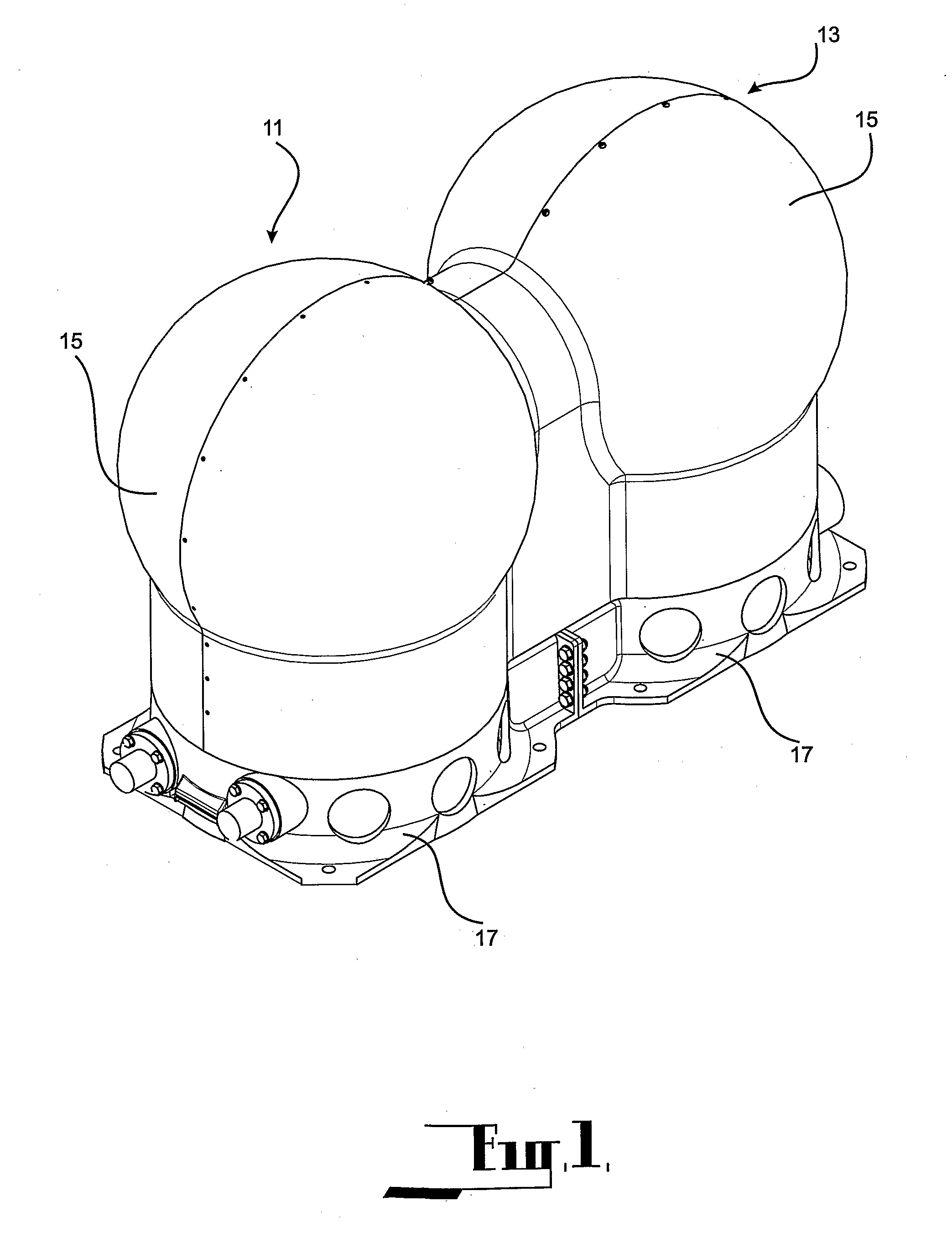
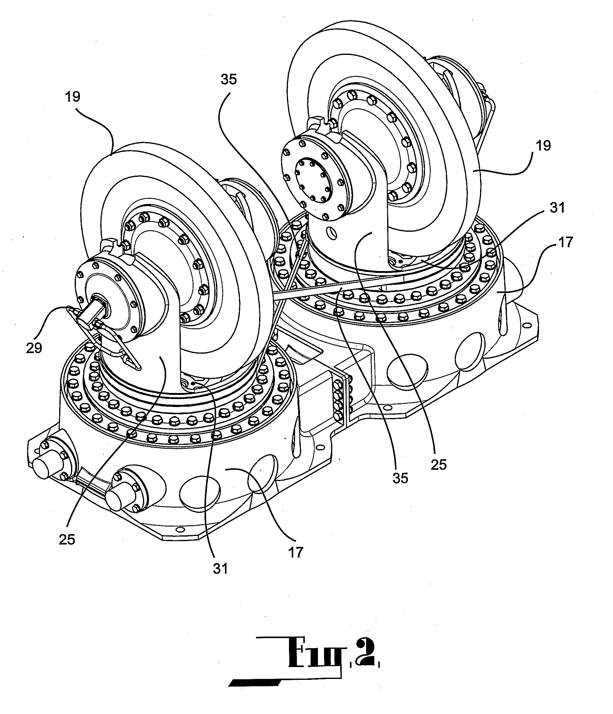
[0043]The embodiments each relate to a stabilising means which is intended for use is association with a motor yacht, commercial transport vessel or military vessel. In the past the application of a stabilising means utilising a gyroscopic system has been impractical in motor yachts because of the mass of the system and the volume occupied by such systems and the difficulty of servicing the rotors of such systems. In motor yachts, a large proportion of their operating time is spent stationary or moving at low speeds and under these conditions the rolling action which can be applied to the vessel by sea conditions can be very undesirable. Therefore it is desirable to minimise the amount of rolling action applied to a vessel.

[0044]The first embodiment as shown at FIGS. 1 to 5 comprises a stabilising means which is intended for installation in a motor yacht, commercial transport vessel or military vessel where the stabilisation axis is parallel to the fore and aft axis of the vessel. T...


PUM


Abstract

A vehicle stabilising means comprising a cradle (23) supported from a mounting (17) to lie to one side of the mounting, a rotor (19) supported from the cradle between a pair of spaced supports (25) to be rotatably supported by the supports, a drive coupled to the rotor enabling the rotor to rotate at a substantially constant angular velocity, the rotor being rotatable about a first axis, the supports located to the side of the cradle remote from the mounting, the cradle further comprises a base (31) which is rotatably supported from the mounting to be rotatable around a second axis which is perpendicular to the first axis of rotation of the rotor and which intersects the first axis of the rotor, the mounting intended in use to be fixed to the vehicle such that in operation the mean orientation of the first and second axes are substantially perpendicular to the direction of the axis of stabilisation.

Description

FIELD OF THE INVENTION[0001]This invention relates to a stabilising means which can be utilised with mobile platforms such as vehicles and throughout the specification the term “vehicle” shall be taken to comprise any form of waterborne, land borne or airborne vehicle capable of moving through the relevant medium and furthermore shall be taken to include platforms which are substantially stationary and are essentially suspended such as those floating on water, those that are airborne and even those in outer space where it is desired to maintain the platform substantially stationary. An example of a stationary platform is a floating drilling platform which is maintained in station over a drilling site.[0002]A particular application of the invention relates to a stabilising means which can be utilised with waterborne vessels. The stabilising means according to the invention utilises a gyroscopic system. Gyroscopic stabilising systems have been proposed in the past but because of their...

Claims


Application Information

Patent Timeline
IPC IPC(8): B63B39/04B62D37/00G01C19/06
CPCB62D37/06B63B39/04Y10T74/1221Y10T74/1225G01C19/16
Inventor ELMS, ANTHONY RICHARD
Owner VEEM
Learn More