Deflection rod system for spine implant with end connectors and method

a technology of end connectors and deflection rods, which is applied in the field of deflection rod systems for spine implants with, can solve problems such as back pain

Inactive Publication Date: 2008-12-11
SPARTEK MEDICAL
View PDF101 Cites 96 Cited by
  • Summary
  • Abstract
  • Description
  • Claims
  • Application Information

AI Technical Summary

Problems solved by technology

Back pain is a significant clinical problem and the annual costs to treat it, both surgical and medical, is estimated to be over $2 billion.

Method used


Image

  • Deflection rod system for spine implant with end connectors and method
  • Deflection rod system for spine implant with end connectors and method
  • Deflection rod system for spine implant with end connectors and method

Examples


Embodiment Construction

[0157]Embodiments of the present invention include a system or implant and method that can dynamically stabilize the spine while providing for preservation of spinal motion. Alternative embodiments can be used for spine fusion.

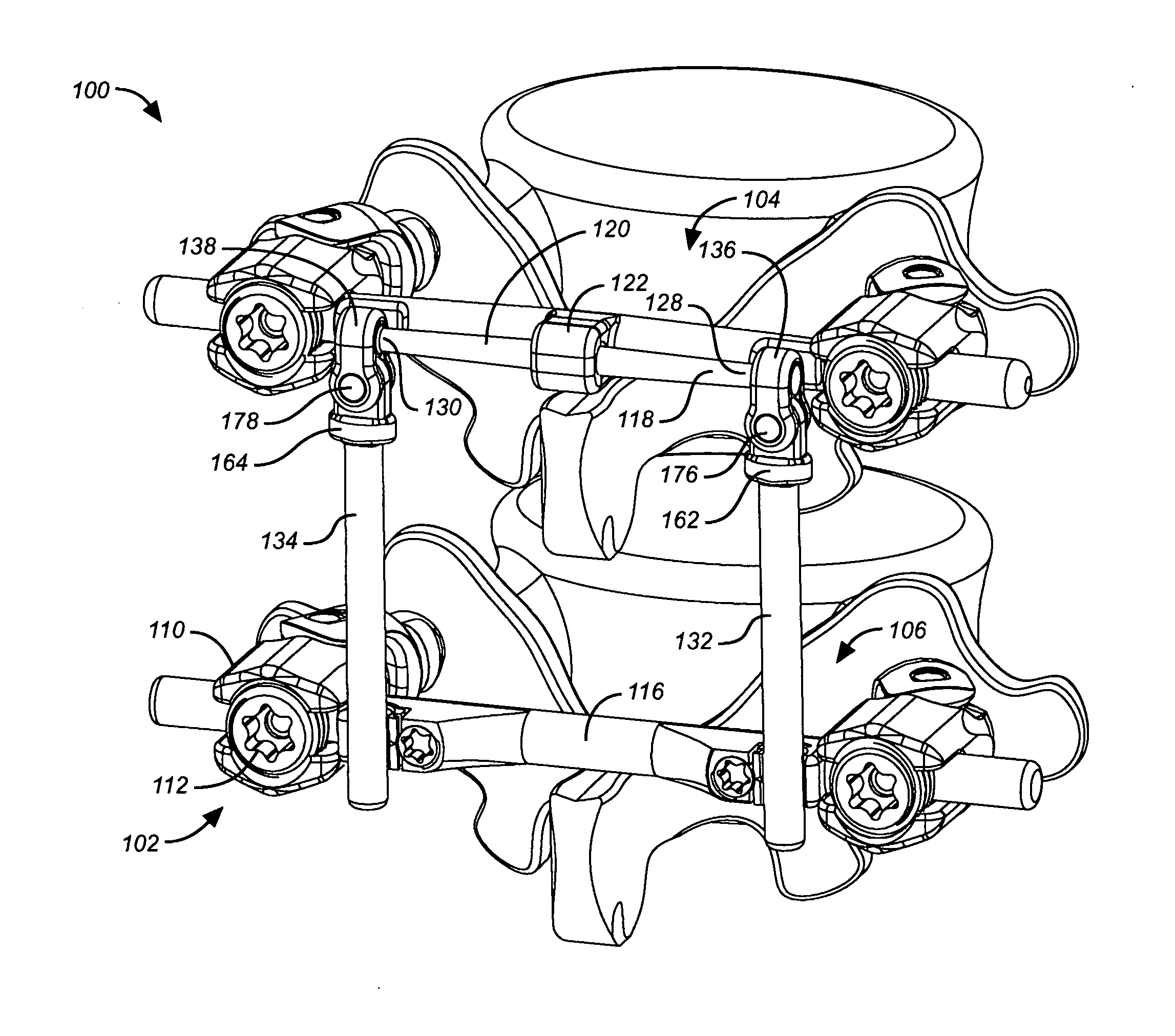
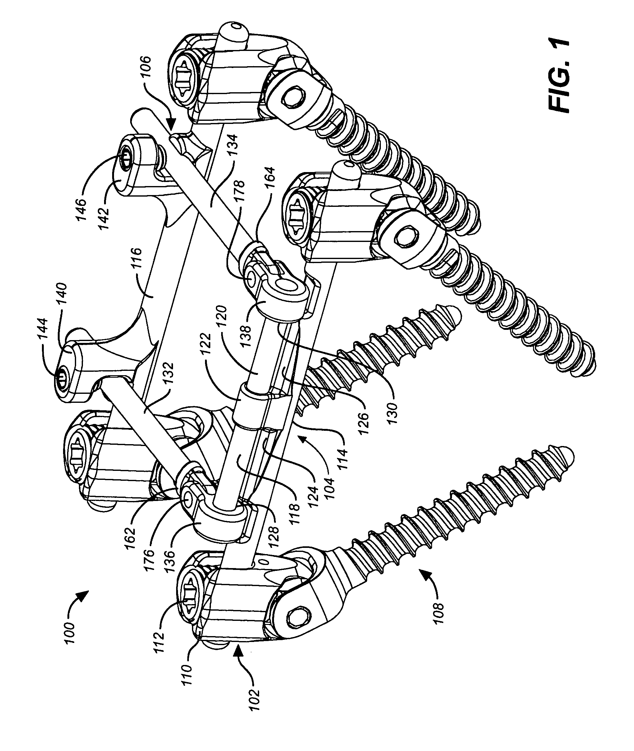
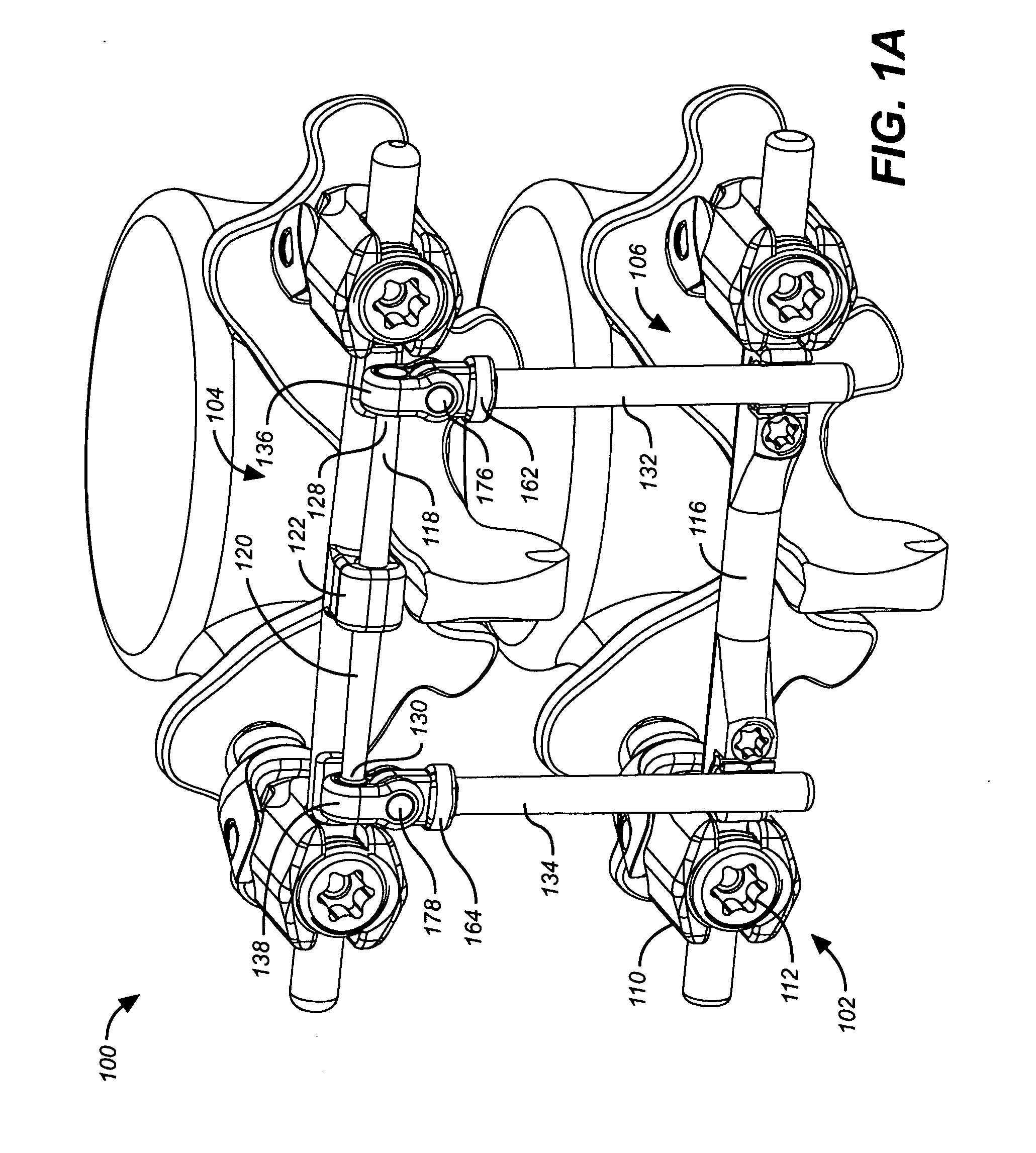
[0158]Embodiments of the invention include a construct with an anchoring system, a horizontal rod system that is associated with the anchoring system and a vertical rod system that is associated with the anchoring system and the horizontal rod system.

[0159]An advantage and aspect of the system is that the anchoring system includes a head or saddle that allows for appropriate, efficient and convenient placement of the anchoring system relative to the spine in order to reduce the force that is placed on the anchoring system. The anchor system has enhanced degrees of freedom which contribute to the ease of implantation of the anchor system. Accordingly, the anchor system is designed to isolate the head and the screw from the rest of the dynamic stabilization syst...


PUM


Abstract

A dynamic stabilization, motion preservation spinal implant system includes an anchor system, a horizontal rod system and a vertical rod system. The systems are modular so that various constructs and configurations can be created and customized to a patient.

Description

CLAIM TO PRIORITY[0001]This application claims priority to all of the following applications including U.S. Provisional Application No. 60 / 942,162, filed Jun. 5, 2007, entitled “Dynamic Stabilization and Motion Preservation Spinal Implantation System and Method” (Attorney Docket No. SPART-01010US0),[0002]U.S. patent application Ser. No. 11 / 832,260, filed Aug. 1, 2007, entitled “Shaped Horizontal Rod for Dynamic Stabilization and Motion Preservation Spinal Implantation System and Method” (Attorney Docket No. SPART-01006US0),[0003]U.S. patent application Ser. No. 11 / 832,273, filed Aug. 1, 2007, entitled “Multi-directional Deflection Profile for a Dynamic Stabilization and Motion Preservation Spinal Implantation System and Method” (Attorney Docket No. SPART-01007US0),[0004]U.S. patent application Ser. No. 11 / 832,305, filed Aug. 1, 2007, entitled “A Horizontal Rod with a Mounting Platform for a Dynamic Stabilization and Motion Preservation Spinal Implant System and Method” (Attorney Doc...

Claims


Application Information

Patent Timeline
Patent Type & Authority Applications(United States)
IPC IPC(8): A61B17/70A61F2/44
CPCA61B17/66A61B17/7026A61B17/7035A61B17/7037A61B17/7041A61B17/7043A61B17/7049
Inventor WINSLOW, CHARLES J.FLYNN, JOHN J.ZUCHERMAN, JAMES F.HSU, KEN Y.CAIN, DONALD L.KLYCE, HENRY A.KLYCE, H. ADAM R.
Owner SPARTEK MEDICAL
Why Eureka
Try Eureka