Cable Cover for an Ultrasonic Flow Meter

a flow meter and ultrasonic technology, applied in the direction of volume metering, simultaneous indication of multiple variables, instruments, etc., can solve the problems of being exposed to the surrounding environment and prone to damag

Active Publication Date: 2008-12-18
MICRO MOTION INC
View PDF5 Cites 25 Cited by
  • Summary
  • Abstract
  • Description
  • Claims
  • Application Information

AI Technical Summary

Problems solved by technology

Because the cables run along the outer surface of the ultrasonic flow meters, they are exposed to the surrou...

Method used


Image

  • Cable Cover for an Ultrasonic Flow Meter
  • Cable Cover for an Ultrasonic Flow Meter
  • Cable Cover for an Ultrasonic Flow Meter

Examples


Embodiment Construction

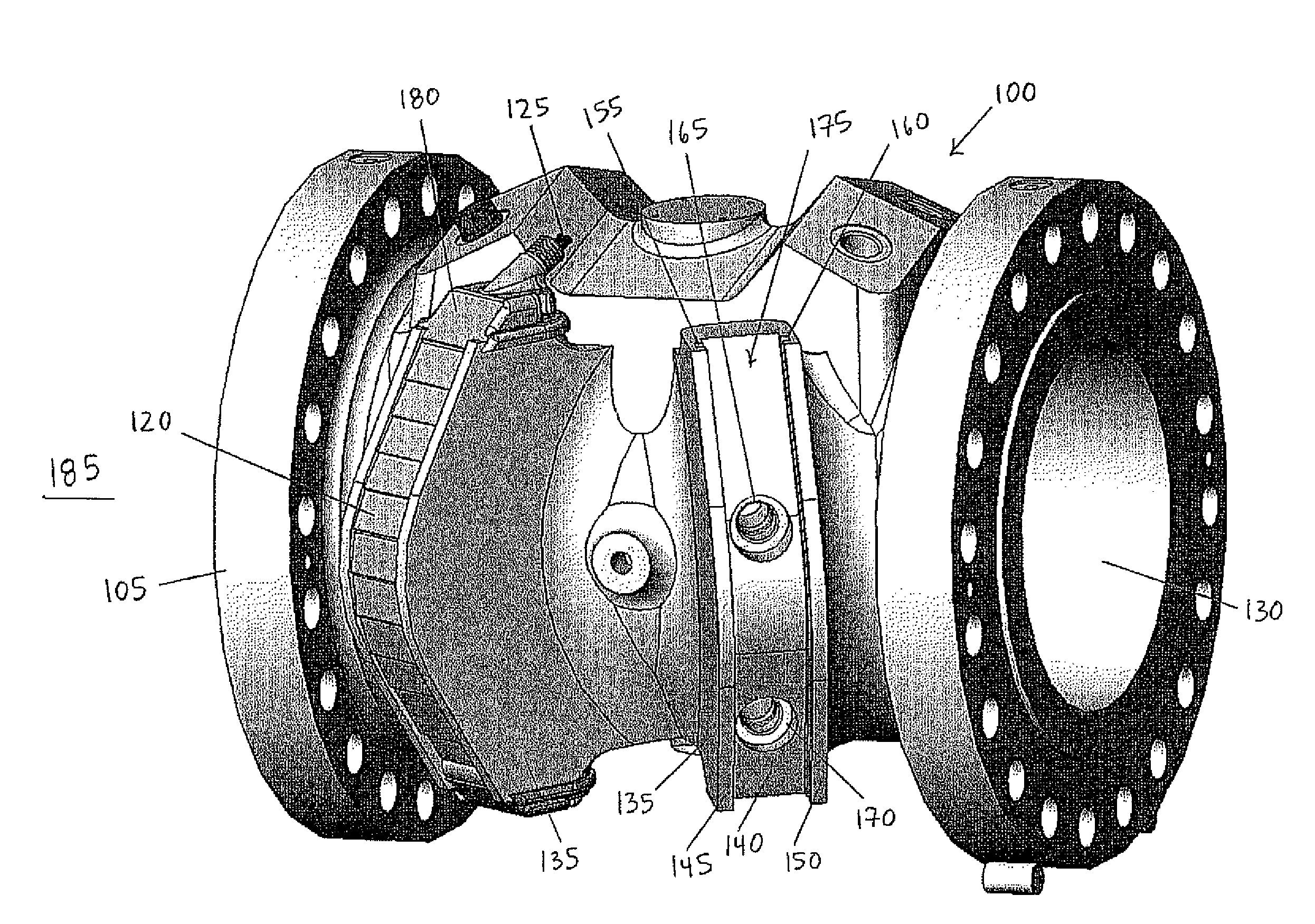
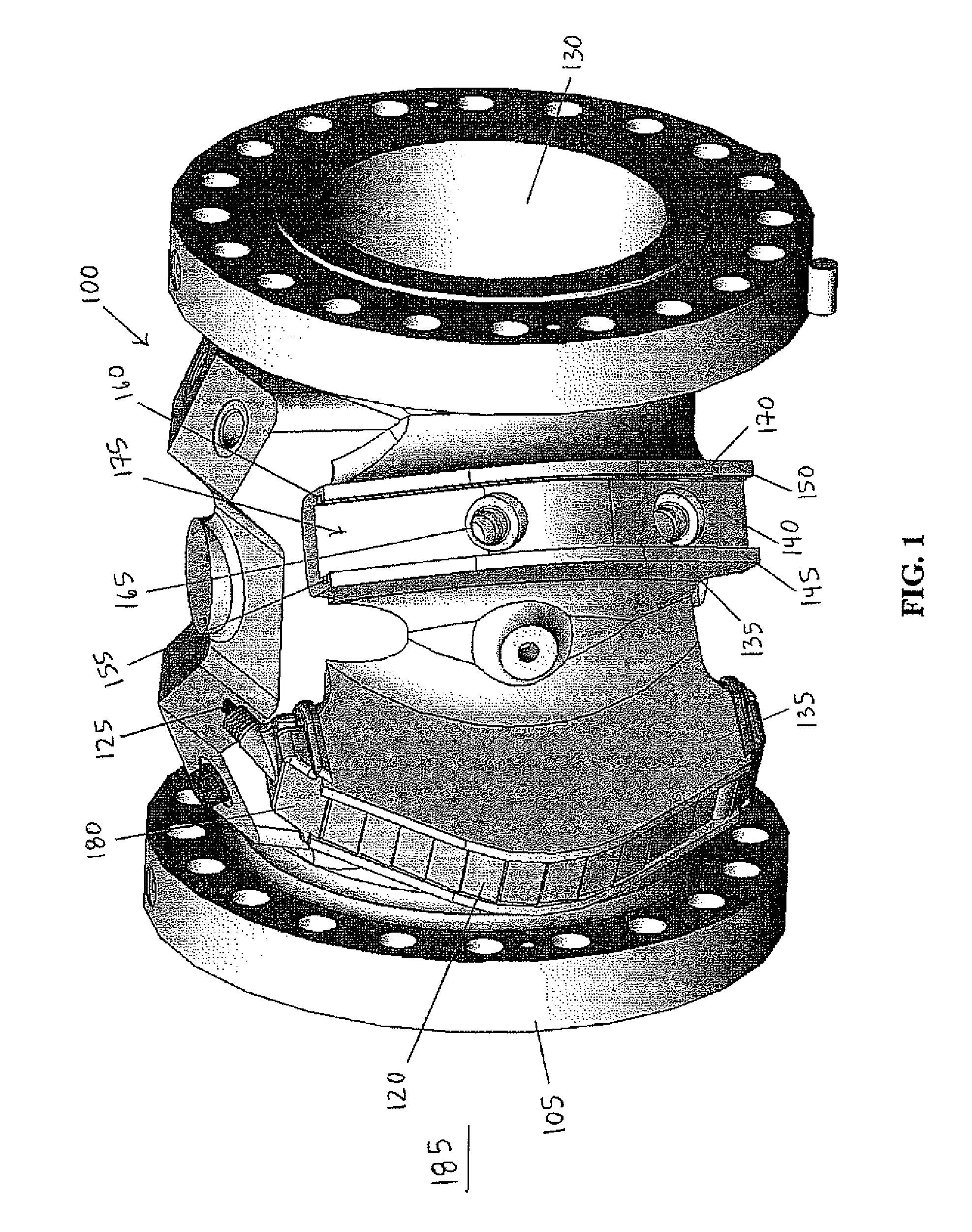
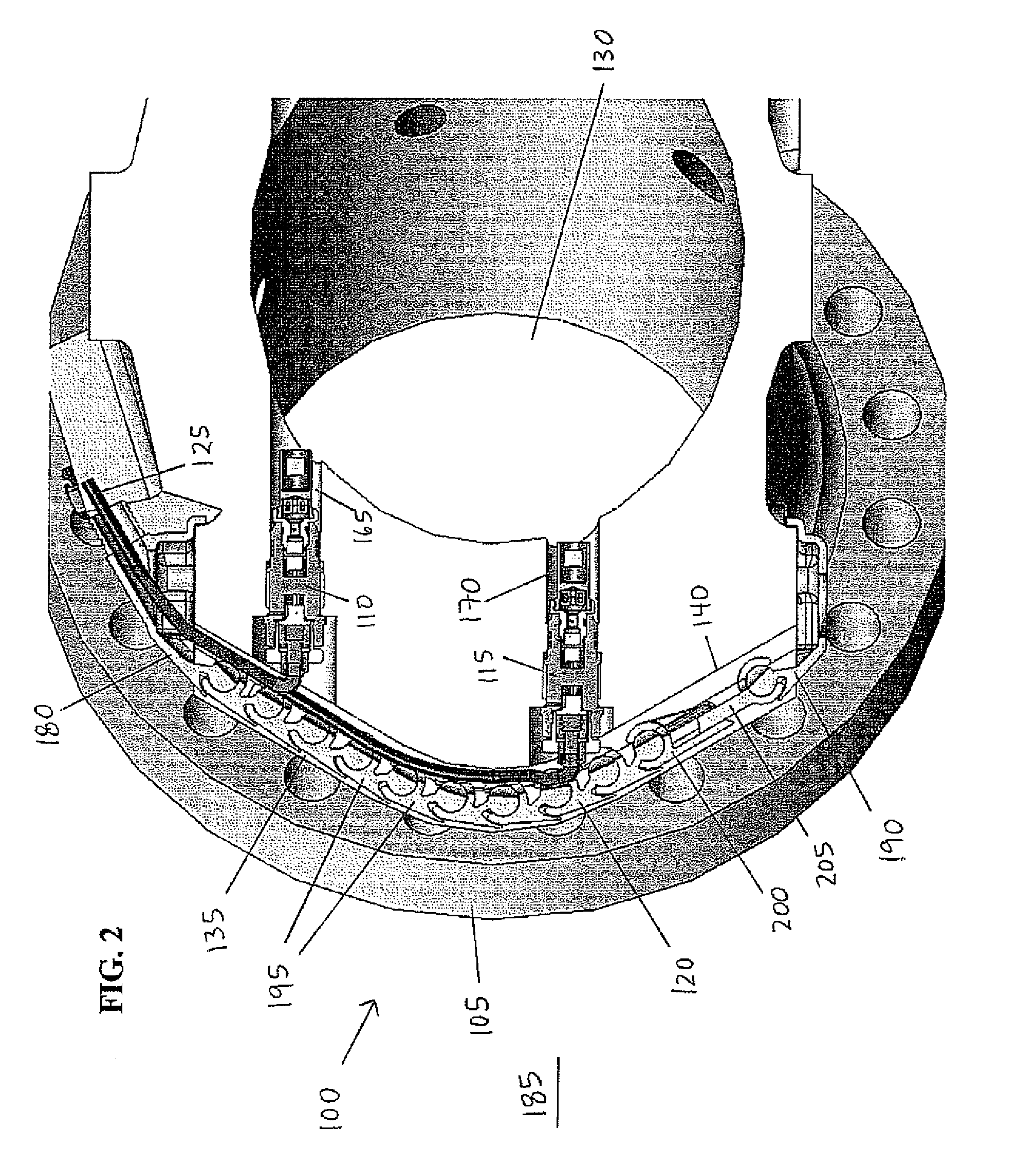
[0024]FIGS. 1 and 2 are perspective and cross-sectional views, respectively, of an ultrasonic flow meter with a cable cover in accordance with various embodiments. Ultrasonic flow meter 100 includes spoolpiece 105, two transducers 110, 115, cable cover 120, and cables 125. Spoolpiece 105 is the housing for ultrasonic flow meter 100 and configured for placement between sections of a pipeline. Spoolpiece 105 further includes bore 130 therethrough and two transducer bosses 135 located along its circumference. A fluid may flow through bore 130. Although two transducer bosses 135 are shown, spoolpiece 105 may include as few as one or more than two transducer bosses 135.

[0025]Each transducer boss 135 further includes recessed face 140, sides 145, 150, side grooves 155, 160, and transducer ports 165, 170. Face 140 and sides 145, 150 form pocket 175 therebetween. Side groove 155 extends along the surface of side 145 bordering pocket 175. Similarly, side groove 160 extends along the surface ...


PUM

PropertyMeasurementUnit
Volumeaaaaaaaaaa
Flexibilityaaaaaaaaaa

Abstract

A cable cover for an ultrasonic flow meter is disclosed. In some embodiments, the cable cover includes multiple interlockable pieces configured to couple to a spoolpiece of an ultrasonic flow meter. Each interlockable piece includes a body having a dowel and a slot. The interlockable pieces are assembled in a series with the dowel of each interlockable piece inserted into the slot of another interlockable piece.

Description

CROSS-REFERENCE TO RELATED APPLICATIONS[0001]Not applicable.STATEMENT REGARDING FEDERALLY SPONSORED RESEARCH OR DEVELOPMENT[0002]Not applicable.BACKGROUND[0003]1. Field of Art[0004]The various embodiments relate to ultrasonic flow meters. More particularly, the various embodiments relate to a novel method and apparatus for protecting cables extending from transducers in ultrasonic flow meters.[0005]2. Description of the Related Art[0006]After hydrocarbons have been removed from the ground, the fluid stream (such as crude or natural gas) is transported from place to place via pipelines. It is desirable to know with accuracy the amount of fluid flowing in the stream, and particular accuracy is demanded when the fluid is changing hands, or “custody transfer.” Even where custody transfer is not taking place, however, measurement accuracy is desirable.[0007]Ultrasonic flow meters may be used in situations such as custody transfer. In an ultrasonic flow meter, ultrasonic signals are sent ...

Claims


Application Information

Patent Timeline
IPC IPC(8): G01D5/12H01R4/22H05K7/14G01F15/00G01F1/66
CPCY10T29/49005G01F1/662
Inventor ALLEN, CHARLES ROBERT
Owner MICRO MOTION INC
Why Eureka
Try Eureka