Stator and Motor, to Which the Stator is Applied, and Method of Manufacturing the Stator

a technology of stator and motor, applied in the field of stator, can solve the problems of motor efficiency deterioration, eddy current loss, and higher cost of electromagnetic steel sheet used for adhesion iron core, and achieve the effect of low price, high efficiency and low cos

Inactive Publication Date: 2008-12-25
PANASONIC CORP
View PDF7 Cites 11 Cited by
  • Summary
  • Abstract
  • Description
  • Claims
  • Application Information

AI Technical Summary

Benefits of technology

[0011]By this constitution and the manufacturing method, it is possible to provide a stator and a highly efficient small motor of low price, to which this stator is applied, without increasing an eddy current loss and without lowering a space factor of the iron core.

Problems solved by technology

Therefore, a motor efficiency is deteriorated.
Even in the second engineering method, an eddy current loss is caused at an engagement portion in which a protruding portion and a recessing portion made by half blanking are engaged with each other.
In general, a cost of this electromagnetic steel sheet used for adhesion iron core is higher than a cost of the electromagnetic steel sheet on which inorganic coating material is coated.
Accordingly, the cost of the divided fixing iron core is raised.
In the conventional stator and the engineering method of manufacturing the stator, the following problems may be encountered when the divided iron core sheets are laminated and fixed.
That is, an eddy current loss of the laminated iron core obtained by the laser welding or the dowel caulking system is large.
A space factor of the laminated iron core obtained by the adhesion lamination engineering method is low and the manufacturing cost is high.
Accordingly, it takes much labor to arrange the iron cores for lamination.

Method used


Image

  • Stator and Motor, to Which the Stator is Applied, and Method of Manufacturing the Stator
  • Stator and Motor, to Which the Stator is Applied, and Method of Manufacturing the Stator
  • Stator and Motor, to Which the Stator is Applied, and Method of Manufacturing the Stator

Examples


embodiment 1

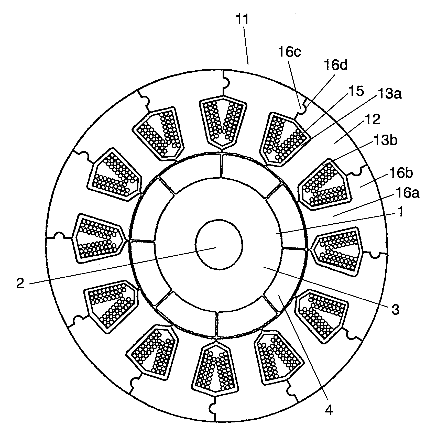
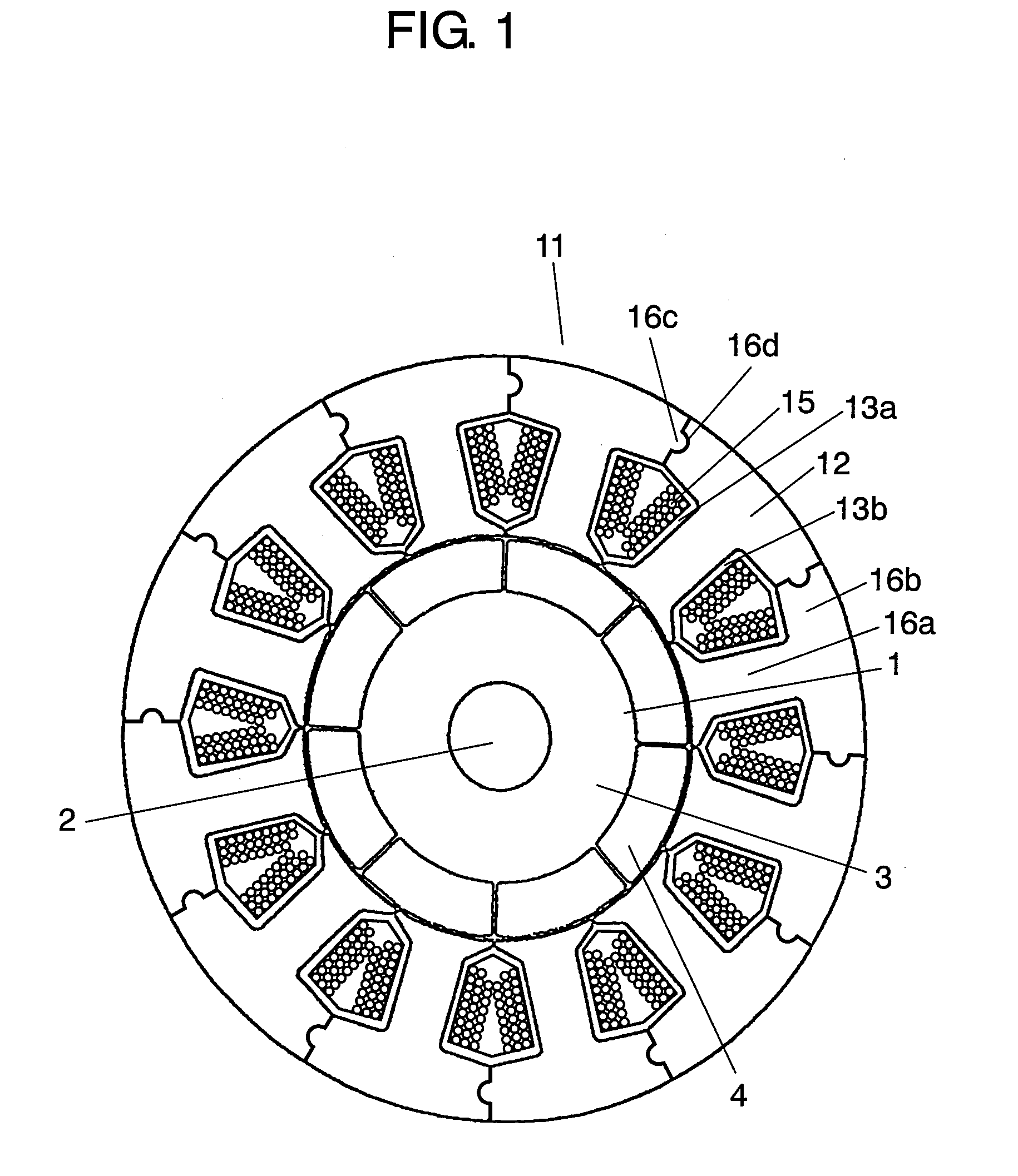
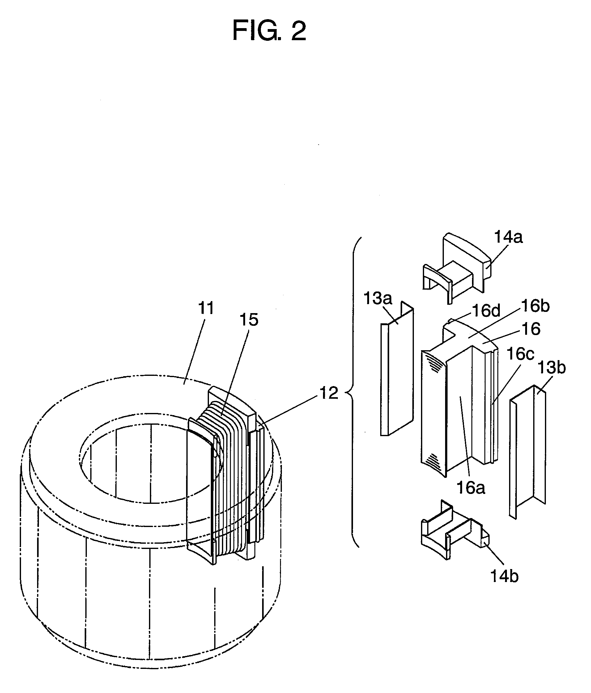
[0036]FIG. 1 is a sectional view of a motor of Embodiment 1 of the present invention. As the motor of the present embodiment, an inner rotor type 8-pole-12-slot type motor is exemplarily shown here. In FIG. 1, stator 11 is composed in such a manner that twelve divided stators 12 are annularly connected to each other. Concerning joining faces of yoke portion 16b of each divided stator 12, recess portion 16d is provided at one of the joining faces and protruding portion 16e is provided at the other face of the joining faces. Due to this constitution, it is possible to conduct positioning and to ensure a mechanical strength.

[0037]Around teeth portion 16a of each divided stator 12, concentrated winding 15 is wound through insulating bodies 13a, 13b before conducting a connection.

[0038]On the other hand, 8 poles of permanent magnets 4, that is, 4 pairs of permanent magnets 4 are fixed onto an outer periphery of rotor iron core 3 of rotor 1. In this case, one pair of permanent magnets inc...

embodiment 2

[0042]FIG. 3 is a schematic illustration for showing an essential part of stator 21 of Embodiment 2 of the present invention. Divided lamination iron core 26 of this embodiment includes recess portion 26e on an outer periphery of the yoke portion. By this recess portion 26e, divided iron core sheets, which have been obtained by punching out an electromagnetic sheet with a metallic press die, are continuously discharged. Therefore, it becomes easy to take out a certain number of divided iron core sheets and to conduct a winding work. Except for that, the essential constitution is the same as that of Embodiment 1.

[0043]A certain number of divided iron core sheets, which are made by punching an electromagnetic steel sheet into a certain shape, are laminated on each other, so that divided lamination iron core 26 can be obtained. This divided lamination iron core 26 is held by an iron core holding jig as described later, however, portions between the divided iron core sheets are not fixe...


PUM

PropertyMeasurementUnit
electric poweraaaaaaaaaa
eddy current lossaaaaaaaaaa
electromagneticaaaaaaaaaa

Abstract

There is provided a stator in which a plurality of divided stators are annularly combined with each other, and each divided stator includes: a divided lamination iron core having teeth portion and a yoke portion, and constructed by laminating electromagnetic steel sheets divided by the teeth unit; insulating bodies provided at the divided lamination iron core; and concentrated winding wound around the divided lamination iron core through the insulating body. In this case, the divided lamination iron core is held by the insulating bodies and the concentrated winding.

Description

TECHNICAL FIELD[0001]The present invention relates to a stator in which a loss caused by lamination of electromagnetic steel sheets is reduced. The present invention also relates to a structure of a motor to which the stator is applied and a method of manufacturing the stator.BACKGROUND ART[0002]Concerning motors mainly used for industrial devices, it is desired to provide small and highly efficient motors so as to reduce electric power consumption. In order to accomplish the above object, highly efficient small motors are mainly used in which an iron core of a stator is divided by the teeth unit and concentrated winding is wound around the divided iron core so that a space factor of a slot winding can be enhanced and a space necessary for a winding end portion can be reduced.[0003]Concerning the engineering method in which a certain number of the divided iron core sheets, which are made by punching an electromagnetic steel sheet, are laminated and fixed on each other so as to obtai...

Claims


Application Information

Patent Timeline
Patent Type & Authority Applications(United States)
IPC IPC(8): H02K1/12H02K15/02
CPCH02K3/325Y10T29/49078Y10T29/49009H02K3/522H02K1/18
Inventor MORIOKA, MASAYUKIMATSUSHITA, YASUAKIKIRA, YOSHIHIROTAMURA, SHINYA
Owner PANASONIC CORP
Why Eureka
Try Eureka