Electric motor

a technology of electric motors and motors, applied in the direction of windings, dynamo-electric components, synchronous machines, etc., can solve the problems of affecting the insulation performance of conductive wires, hindering the alignment of windings, and preventing winding operations, etc., to achieve the effect of high space factor

Active Publication Date: 2015-02-05
FUJITSU GENERAL LTD
View PDF4 Cites 7 Cited by
  • Summary
  • Abstract
  • Description
  • Claims
  • Application Information

AI Technical Summary

Benefits of technology

[0012]According to the present invention, the inner peripheral surface of the outer peripheral wall portion of the insulator on the winding body portion side includes the planar portion perpendicular to the direction in which the winding body portions protrude. The outer peripheral surface of the outer peripheral wall portion on the winding body portion side is formed in an arc shape. The radial thickness of the outer peripheral wall portion is increased toward the circumferential center of the winding body portion. Thus, there is obtained the effect that the inward falling of the outer peripheral wall portion of the insulator is difficult to occur, and that the winding can be wound on the winding body portions at high space factor.

Problems solved by technology

This may lead to a problem in that the insulating performance of the conductive wire is adversely affected by frictional rubbing caused, for example, during the operation of the electric motor or by vibrations due to the flow velocity of refrigerant.
However, such ribs on the winding body portions 82 would provide an obstacle to the winding operation and hinder aligned winding.

Method used


Image

  • Electric motor
  • Electric motor
  • Electric motor

Examples


embodiments

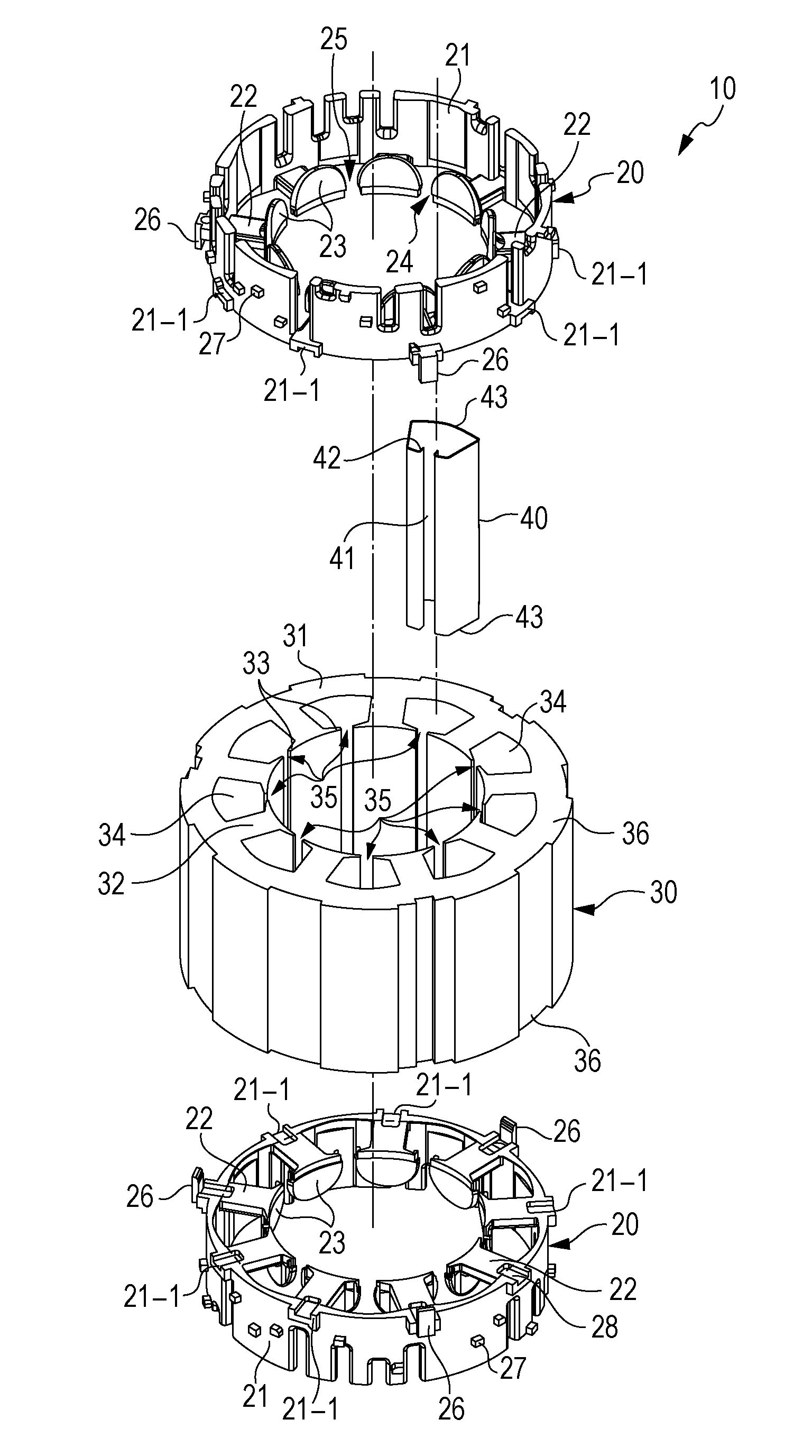
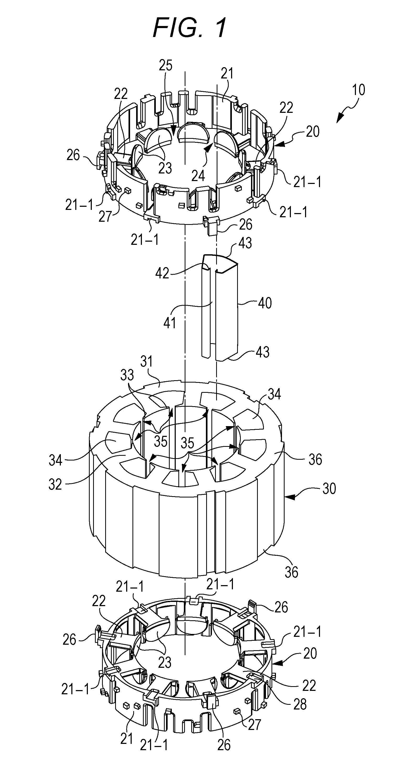
[0024]FIG. 1 is an exploded perspective view of a stator of an electric motor according to the present invention. FIG. 2 is an enlarged perspective view of an upper insulator of FIG. 1. FIG. 3 is an enlarged perspective view of a lower insulator of FIG. 1. FIG. 4 is a plan view of the insulator of FIG. 3 as viewed from above. FIG. 5-1 is a partially enlarged plan view of the insulator of FIG. 2 as viewed from above. FIG. 5-2 is another partially enlarged plan view of the insulator of FIG. 2 as viewed from above. FIG. 6 is a cross sectional view taken along line A-A′ in FIG. 4. FIG. 7 is a cross sectional view taken along line A-O-B in FIG. 4. FIG. 8 is a transition diagram plotting the degrees of falling of an outer peripheral wall portion toward the radially inner side due to variation with time, measured for the insulators according to the present embodiment and a plurality of comparative examples.

[0025]As illustrated in FIG. 1, a stator 10 of the electric motor according to the p...


PUM


Abstract

The electric motor includes a rotor and a stator, the stator having a conductive wire wound thereon via a stator core and insulators. The insulators include an annular outer peripheral wall portion with the conductive wire run on an outer periphery side of the peripheral wall portion, a plurality of winding body portions protruding radially from the outer peripheral wall portion, and an inner flange portion. The outer peripheral wall portion on the winding body portion side includes an outer peripheral surface formed in an arc shape. The radial thickness of the outer peripheral wall portion is increasingly greater toward the circumferential center of the winding body portions.

Description

TECHNICAL FIELD[0001]The present invention relates to an electric motor including a rotor and a stator disposed outside the rotor.BACKGROUND ART[0002]Conventionally, an electric motor used in a compressor or the like of an air conditioner or refrigerator includes a rotor and a tubular stator radially disposed outside the rotor. The stator includes a stator core and insulators disposed facing the opposite axial both end surfaces of the stator core. The insulators are formed of an insulating material, such as resin.[0003]Referring to FIG. 9, a conventional insulator 80 includes a cylindrical outer peripheral wall portion 81, a plurality of winding body portions 82, and inner flange portions 83. The winding body portions 82 protrude radially from the outer peripheral wall portion 81 toward the inner side in the radial direction. The inner flange portions 83 rise from the inner ends of the respective winding body portions 82 in the axial direction of the cylinder. An insulator opening 8...

Claims


Application Information

Patent Timeline
Patent Type & Authority Applications(United States)
IPC IPC(8): H02K3/28H02K3/32H02K3/46
CPCH02K3/28H02K3/32H02K3/46H02K3/345H02K3/522H02K15/095H02K2203/12H02K3/34
Inventor TAEMA, YOSHIHIRO
Owner FUJITSU GENERAL LTD
Why Eureka
Try Eureka