Stator for rotating electric machine

Active Publication Date: 2015-08-13
DENSO CORP
View PDF19 Cites 7 Cited by
  • Summary
  • Abstract
  • Description
  • Claims
  • Application Information

AI Technical Summary

Benefits of technology

[0021]That is, it is possible to correct the deviation of the circumferential pitch while keeping the axial length and radial width of the coil end portions of the phase windings almost unchanged. Consequently, it is possible to prevent interference between the coil end portions of the phase windings of the stator coil. Moreover, it is also possible to secure a suitable abutting load bet

Problems solved by technology

First, due to the dimensional tolerances of raw materials and the manufacturing tolerances of the stator coil and the stator core, in mounting the stator coil to the stator core, an undesirable load may be imposed on the stator coil, thereby lowering the insulating properties of the stator coil. For example, the coil end portions of the phase windings of the stator coil may interfere with one other, thereby damaging insulating coats formed on the outer surfaces of the phase windings.
Secondly, there occurs variation in the mounting strength (or winding strength) of the stator coil to the stator core. In other cases, it is desired to set the mounting strength as needed. For example, when an abutting load higher than a threshold value is applied between th

Method used


Image

  • Stator for rotating electric machine
  • Stator for rotating electric machine
  • Stator for rotating electric machine

Examples


Example

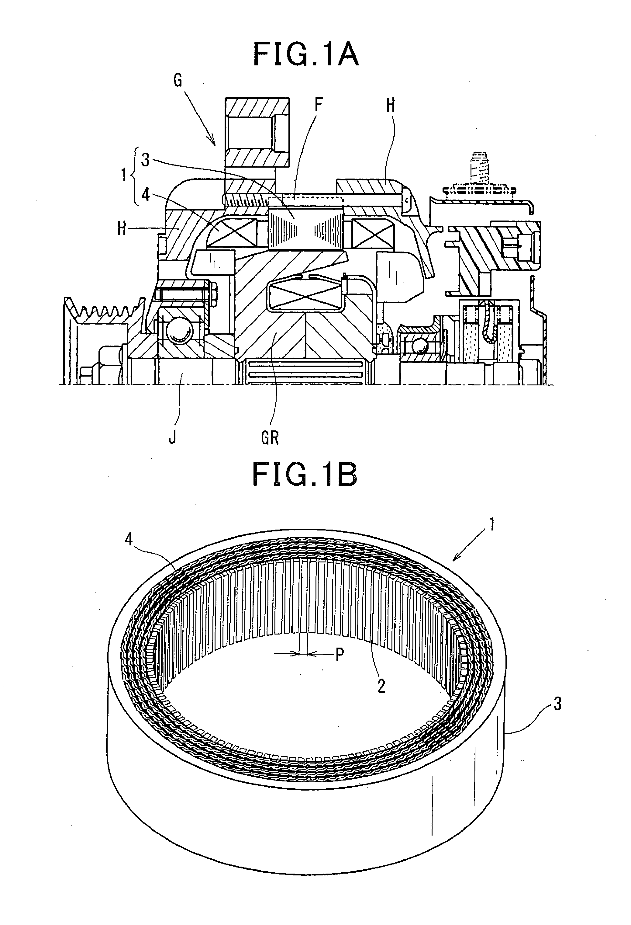
[0041]FIG. 1A shows the overall configuration of a rotating electric machine which includes a stator 1 according to an exemplary embodiment. FIG. 1B shows the overall configuration of the stator 1.

[0042]In the present embodiment, the rotating electric machine is configured as an automotive alternator, i.e., an AC generator G for use in a motor vehicle, such as a passenger car or a truck.

[0043]As shown in FIG. 1A, the alternator G further includes a rotating shaft J, a rotor GR and a pair of substantially cup-shaped housings (or frames) H in addition to the stator 1. The rotating shaft J is configured to be driven by an internal combustion engine (not shown in the figures) of the vehicle. The rotor GR is mounted on the rotating shaft J so as to rotate together with the rotating shaft J. The pair of housings H are assembled together by a plurality of bolts F, so as to have the stator 1 fixedly held (or retained) therebetween.

[0044]In addition, in the alternator G, the rotor GR functio...


PUM


Abstract

A stator includes a multi-phase stator coil comprised of phase windings. Each of the phase windings is formed of a continuous electric conductor and includes in-slot portions and coil end portions. Each of the in-slot portions is received in one of slots of a stator core. Each of the coil end portions is located outside the slots so as to connect one adjacent pair of the in-slot portions. Each of the coil end portions includes at least one oblique part that extends obliquely at an oblique angle with respect to either an axial direction or a circumferential direction of the stator core. The oblique angles of the oblique parts of the coil end portions in at least one of the phase windings of the stator coil are set to be different from the oblique angles of the oblique parts of the coil end portions in the other phase windings.

Description

CROSS-REFERENCE TO RELATED APPLICATION[0001]This application is based on and claims priority from Japanese Patent Application No. 2014-22367 filed on Feb. 7, 2014, the content of which is hereby incorporated by reference in its entirety into this application.BACKGROUND[0002]1 Technical Field[0003]The present invention relates generally to stators for rotating electric machines that are used in, for example, motor vehicles as electric motors and electric generators. More particularly, the invention relates to a stator for an automotive alternator which includes a multi-phase stator coil.[0004]2 Description of Related Art[0005]Conventionally, various types of stators for rotating electric machines have been provided for practical use.[0006]For example, there is disclosed a stator for an automotive alternator in Japanese Patent Application Publication No. JP2010110199A. The stator includes a hollow cylindrical stator core having a plurality of slots arranged in its circumferential dire...

Claims


Application Information

Patent Timeline
IPC IPC(8): H02K3/28H02K3/12
CPCH02K3/12H02K3/28H02K3/00H02K15/0031H02K2213/03
Inventor TOKIZAWA, TAKASHI
Owner DENSO CORP
Why Eureka
Try Eureka