Coil winding device and method for manufacturing coil

a coil and winding device technology, applied in the manufacture of coils, transformer/inductance details, electrical devices, etc., can solve the problems of significantly reduce the proportion occupied, etc., and achieve the effect of improving the space factor of the wire rod and enlarge the outer shape of the coil

Active Publication Date: 2018-02-22
NITTOKU CO LTD
View PDF0 Cites 7 Cited by
  • Summary
  • Abstract
  • Description
  • Claims
  • Application Information

AI Technical Summary

Benefits of technology

[0006]At the coil manufacturing device in JPH10-154626A, since the wire rod having a circular-shaped cross-sectional surface is used, even if the wire rod is twisted to be wound around the winding core, this does not influence its outer shape. However, recently, to improve a space factor of the wire rod, there are many requests to use a rectangular wire rod having a rectangular-shaped cross-sectional surface. In view of this, if such rectangular wire rod is twisted to be wound around the winding core, this reduces a proportion occupied by the rectangular wire rod to generate a trouble that significantly enlarges the outer shape of the coil.
[0007]It is an object of the present invention to provide a coil winding device and a method for manufacturing a coil that ensure winding without twisting the wire rod.

Problems solved by technology

Thus, there is a trouble where this wire rod delivered from the wire rod supply portion is twisted to be wound around the winding core.
In view of this, if such rectangular wire rod is twisted to be wound around the winding core, this reduces a proportion occupied by the rectangular wire rod to generate a trouble that significantly enlarges the outer shape of the coil.

Method used


Image

  • Coil winding device and method for manufacturing coil
  • Coil winding device and method for manufacturing coil
  • Coil winding device and method for manufacturing coil

Examples


Embodiment Construction

[0020]The following describes an embodiment of the present invention with reference to the accompanying drawings.

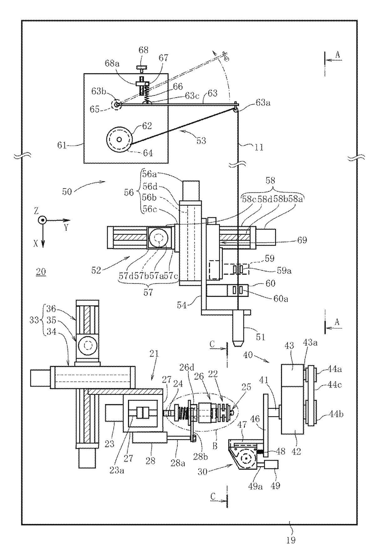
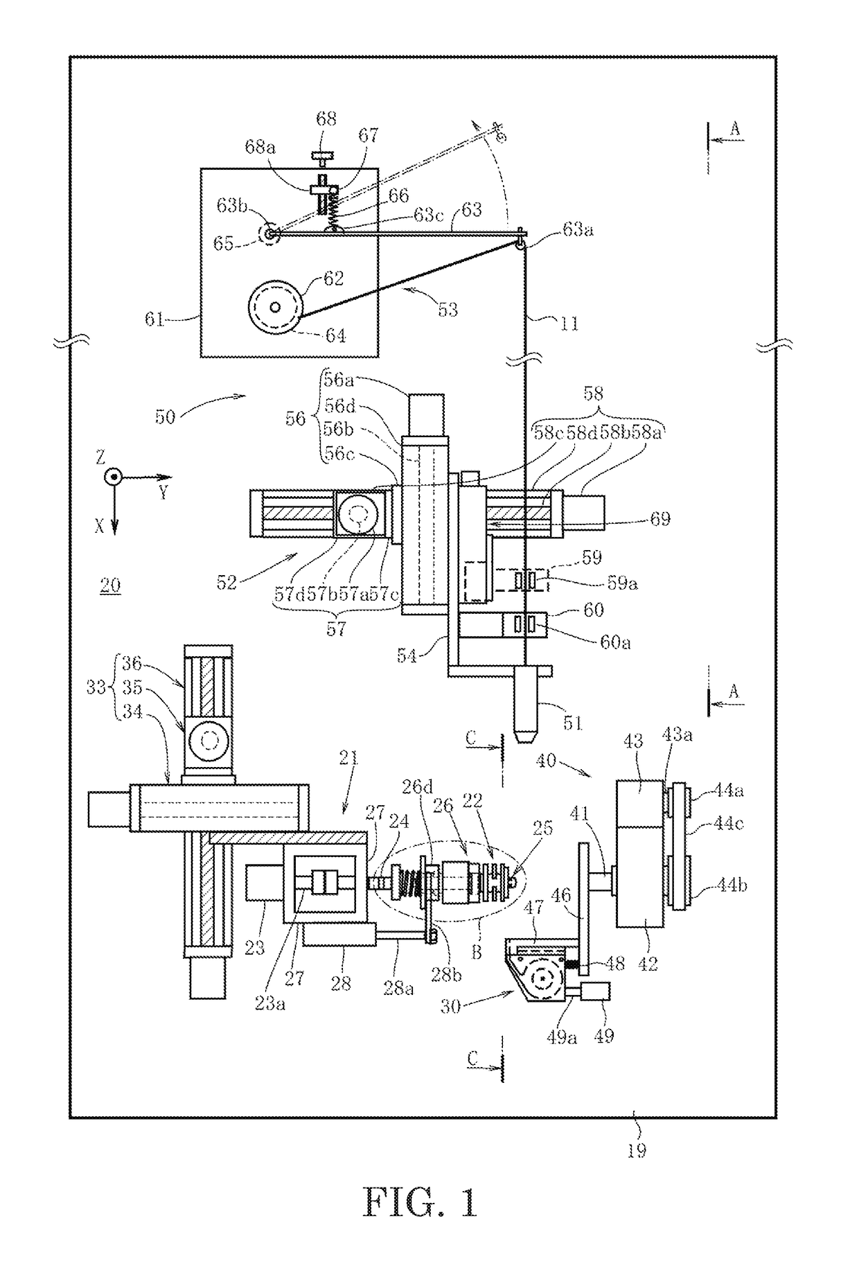
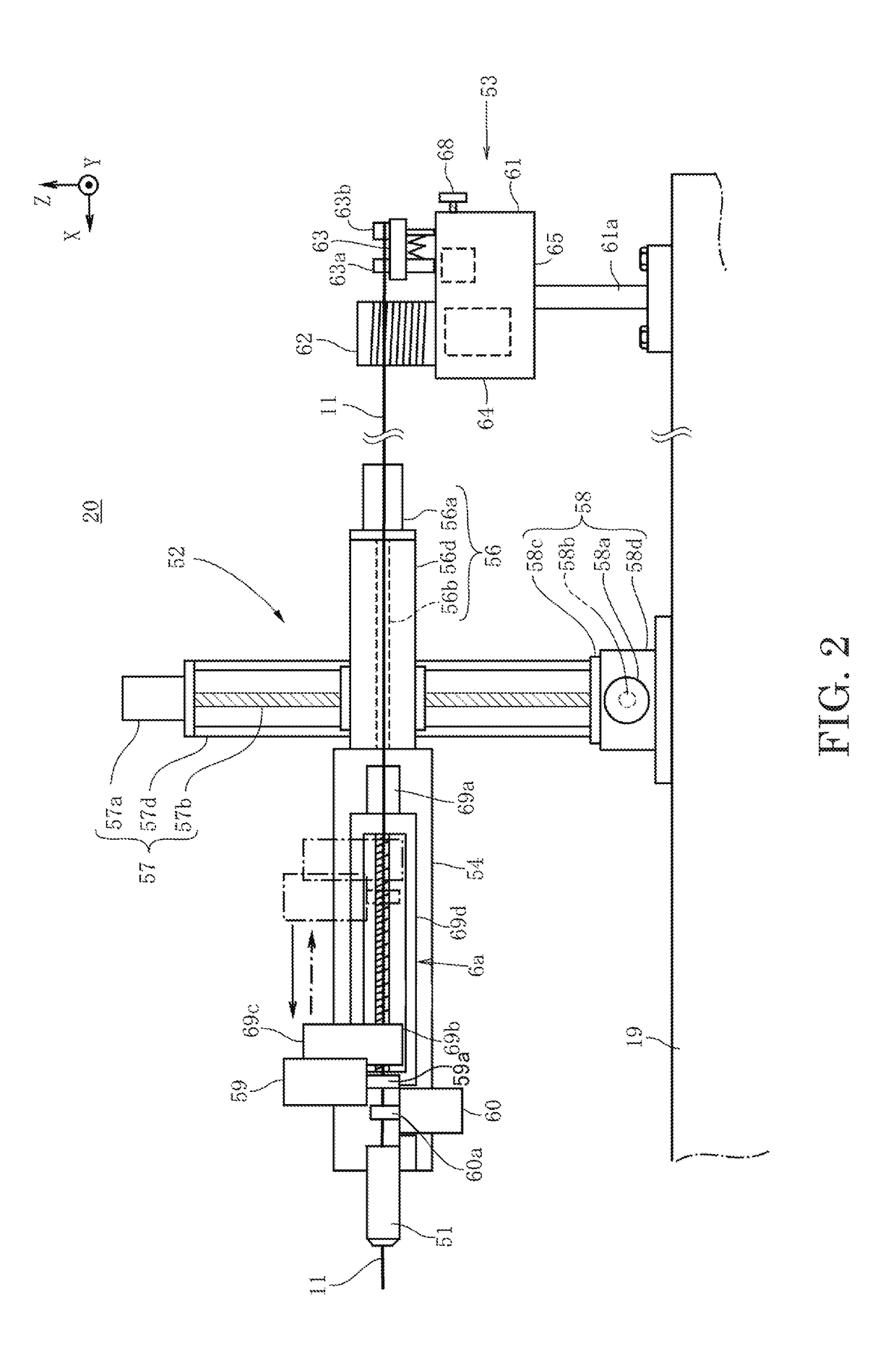
[0021]FIG. 1 illustrates a coil winding device 20 according to the embodiment of the present invention. Here, X, Y, and Z three axes that mutually orthogonal are set. The X-axis extends in an approximately horizontal front-rear direction. The Y-axis extends in an approximately horizontal transverse direction. The Z-axis extends in an approximately vertical direction. Considering them, a configuration of the coil winding device 20 will be described.

[0022]The coil winding device 20 winds a wire rod 11 such that a winding starting end and a winding terminating end are wired at an identical winding layer. The coil winding device 20 includes a wire rod delivering machine 50 disposed on a mounting 19. The wire rod delivering machine 50 delivers the wire rod 11 through a nozzle 51. The wire rod delivering machine 50 includes the nozzle 51, a nozzle moving mechanism 52, and a ten...


PUM

PropertyMeasurementUnit
rotationaaaaaaaaaa
thicknessaaaaaaaaaa
widthaaaaaaaaaa

Abstract

A coil winding device includes a wire rod delivering machine configured to deliver a wire rod through a nozzle, a wire storing jig configured to store the wire rod delivered from the nozzle, a wire-wound member around which the wire rod is wound, a wire-wound-member rotation mechanism configured to rotate the wire-wound member to wind the wire rod delivered from the nozzle around the wire-wound member, and a wire-storing-jig turning mechanism configured to turn the wire storing jig around a rotation axis of the wire-wound member to wind the wire rod delivered from the wire storing jig around the wire-wound member. The rotation axis of the wire-wound member and a wire-storing central axis of the wire storing jig are mutually orthogonal.

Description

TECHNICAL FIELD[0001]The present invention relates to a coil winding device and a method for manufacturing a coil.BACKGROUND ART[0002]Conventionally, to deal with downsizing of a coil, what is called alpha winding (or, “outer-outer winding” in other words) such that a wire rod is closely wound not to form an unnecessary gap between winding layers, and a winding starting end and a winding terminating end of the wire rod are wired at an identical winding layer is heavily used. As this alpha winding coil, a two-row spiral coil has been known. The two-row spiral coil includes first and second coils which is made by winding the wire rod in a spiral, and an inside crossover wire that couples inner peripheral end portions of these first and second coils one another.[0003]As a manufacturing device of the two-row spiral coil, JPH10-154626A proposes a device that includes first and second wheels, a winding wire supply portion, and a wire storing portion. The first and second wheels are oppose...

Claims


Application Information

Patent Timeline
Patent Type & Authority Applications(United States)
IPC IPC(8): H01F41/04H01F41/064H01F41/082
CPCH01F41/04H01F41/064H01F41/082H01F41/088H01F41/061H01F27/2847H01F41/06Y10T29/53143Y10T29/49071
Inventor KANNO, TAKASHISAITO, TATSUYA
Owner NITTOKU CO LTD
Why Eureka
Try Eureka