Liquid jetting head, liquid jetting recording apparatus, and method for filling liquid jetting head with liquid

A technology of liquid jet head and jet body, which is applied in printing and other directions, can solve problems such as printing failure, and achieve the effects of preventing pollution, stabilizing liquid jetting, and improving the degree of freedom

Inactive Publication Date: 2011-11-23
SII PRINTEK
View PDF2 Cites 5 Cited by
  • Summary
  • Abstract
  • Description
  • Claims
  • Application Information

AI Technical Summary

Problems solved by technology

Therefore, there is a problem that printing cannot be performed on the lower portion of the recording medium.

Method used


Image

  • Liquid jetting head, liquid jetting recording apparatus, and method for filling liquid jetting head with liquid
  • Liquid jetting head, liquid jetting recording apparatus, and method for filling liquid jetting head with liquid
  • Liquid jetting head, liquid jetting recording apparatus, and method for filling liquid jetting head with liquid

Examples


no. 1 approach

[0089] (Liquid jet recording device)

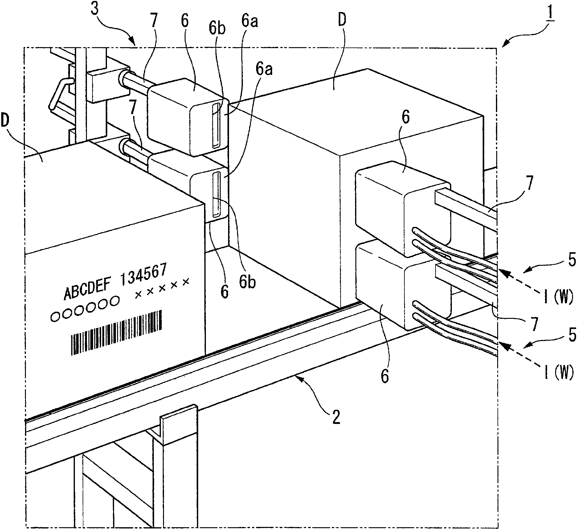
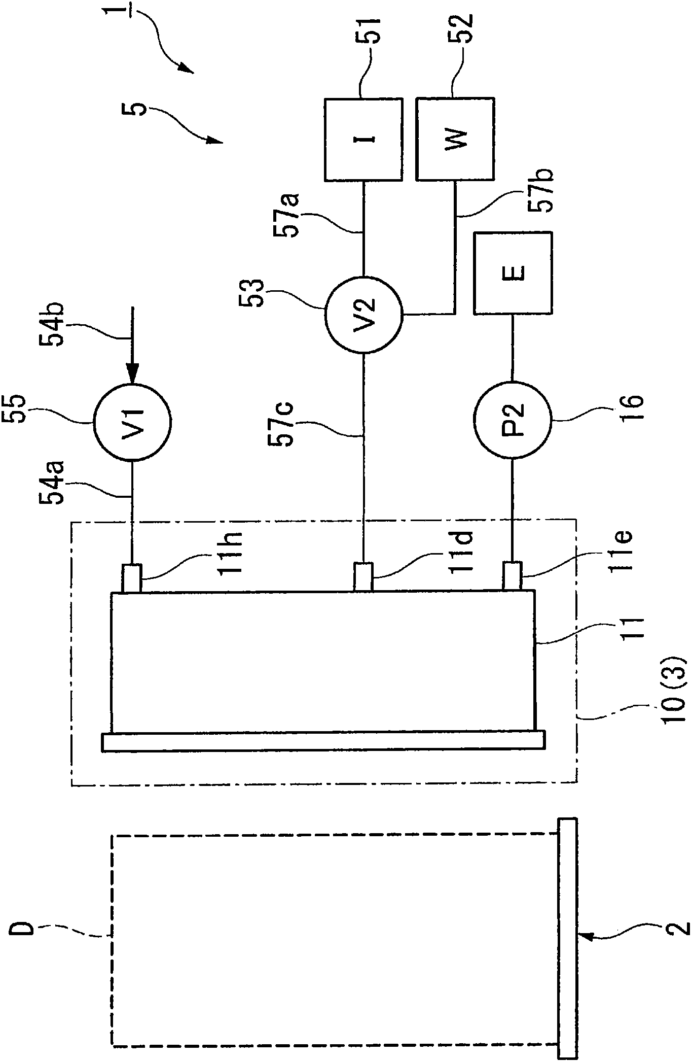
[0090] figure 1 is a perspective view showing an ink jet recording device (liquid jet recording device) 1 according to a first embodiment of the present invention, figure 2 It is a schematic configuration diagram of the inkjet recording device 1 . This inkjet recording device 1 is connected to a designated personal computer, and discharges (ejects) ink (first liquid) I to perform printing on a tank D based on print data transmitted from the personal computer. The inkjet recording apparatus 1 includes a belt conveyor 2, an ink discharge unit 3, an ink supply unit 5, and a suction pump (suction device) 16, wherein the belt conveyor 2 conveys the box D in one direction, and the ink discharge unit 3 includes A plurality of inkjet heads 10, such as figure 2 As shown, the ink supply unit 5 supplies the ink I and the cleaning liquid (second liquid) W to the inkjet head 10 , and the suction pump 16 is connected to the inkjet head 10 .

[00...

no. 2 approach

[0204] Next, a second embodiment of the present invention will be described. Figure 15 is a schematic configuration diagram of the inkjet head 100 of the second embodiment viewed from the right side, Figure 16 Yes Figure 15 Sectional view of line IV-IV.

[0205] Compared with the inkjet head in which the opening and closing mechanism of the above-mentioned first embodiment is configured as a door type, the difference of the inkjet head 100 is that the opening and closing mechanism is configured as a shutter type, and the opening and closing mechanism 110 and the opening and closing mechanism 110 are provided. The absorber 140 of the closing mechanism 110.

[0206] In addition, the same code|symbol is attached|subjected to the member of the same structure as 1st Embodiment mentioned above, and description is abbreviate|omitted.

[0207] like Figure 15 , 16 As shown, the opening and closing mechanism 110 of the inkjet head 100 of this embodiment includes a pair of guide...

no. 3 approach

[0218] Next, a third embodiment of the present invention will be described. In addition, the same code|symbol is attached|subjected to the member of the same structure as 1st Embodiment mentioned above, and description is abbreviate|omitted.

[0219] Figure 17 It is an enlarged cross-sectional view of a main part of the inkjet head 200 of the third embodiment.

[0220] The inkjet head 200 differs from the above-described opening and closing mechanisms 60 and 110 in that the opening and closing mechanism is a sliding door type, and includes an opening and closing mechanism 210 and an absorber 240 .

[0221] like Figure 17 As shown, the opening and closing mechanism 210 of the inkjet head 200 of this embodiment is constituted by the shutter 205 and the sealing member 63 which are supported by the guide part which is not shown in the figure.

[0222] The shutter 205 is a thin plate formed to have a larger opening area than the wall opening 24n, and is guided by guides (not sho...


PUM


Abstract

The space factor of a liquid jetting head is improved, and the degree of freedom in designing a liquid jetting recording apparatus is improved. Performance of recovering a surplus liquid is improved with a simple configuration, contamination due to the surplus liquid is eliminated, the liquid jetting recording apparatus is initially filled, and liquid jetting after the liquid filling is stabilized. The liquid jetting head is provided with: a wall section (24), which surrounds the periphery of a jetting port row and protrudes in the same direction as the opening direction of a jetting port; an opening / closing mechanism (60), which has a cover member (62) that can open / close an opening section (24n) formed by the wall section (24), configures a closed space between the wall section (24) and the jetting body (23) in the closed state, and exposes the jetting port to the outside in the opened state; an absorber (40), which is provided on a rear surface (62b) of the cover member (62) and absorbs the liquid spilled out from the jetting port; a suction channel (15), which has a suction port (15a) opened to the closed space and is connected to an external suction apparatus (8); and a section (33) opened to atmosphere, which can perform switching between opening and blocking of the closed space to and from the outside.

Description

technical field [0001] The present invention relates to a liquid ejection head that ejects liquid from a liquid ejection port to record images or characters on a recording medium, a liquid ejection recording device, and a liquid filling method for the liquid ejection head. Background technique [0002] In general, a liquid jet recording apparatus such as an inkjet printer that performs various types of printing includes a conveyance device that conveys a recording medium and an inkjet head. As the inkjet head used here, there is known an inkjet head comprising a nozzle body (ejection body) having a nozzle row (ejection hole row) composed of a plurality of nozzle holes (ejection hole), and A plurality of pressure generating chambers in which the nozzle holes are paired and communicated with the nozzle holes, an ink supply system for supplying ink to the pressure generating chambers, and piezoelectric actuators arranged adjacent to the pressure generating chambers drive the pi...

Claims


Application Information

Patent Timeline
Patent Type & Authority Applications(China)
IPC IPC(8): B41J2/175B41J2/165B41J2/18B41J2/185
CPCB41J2/16505B41J2/16538B41J2/16552B41J2/045B41J2/055B41J2/175
Inventor 坂田明史富永和由渡边俊显加山文子
Owner SII PRINTEK
Why Eureka
Try Eureka