Bearing device with sensor and rolling bearing with sensor

A technology for rolling bearings and bearing devices, applied in bearing assembly, measuring devices, bearing components, etc., can solve the problems of increasing assembly man-hours, restricting miniaturization, increasing the number of parts and construction costs, and improving tensile strength, reducing assembly man-hours, The effect of reducing the number of parts

Inactive Publication Date: 2005-12-14
NSK LTD
View PDF8 Cites 27 Cited by
  • Summary
  • Abstract
  • Description
  • Claims
  • Application Information

AI Technical Summary

Problems solved by technology

Therefore, it is necessary to arrange other parts such as the shielding plate such as the magnetic shunt 862 in the space between the bearing 850 with the sensor and the magnetic sensor 860, w...

Method used


Image

  • Bearing device with sensor and rolling bearing with sensor
  • Bearing device with sensor and rolling bearing with sensor
  • Bearing device with sensor and rolling bearing with sensor

Examples


no. 1 approach

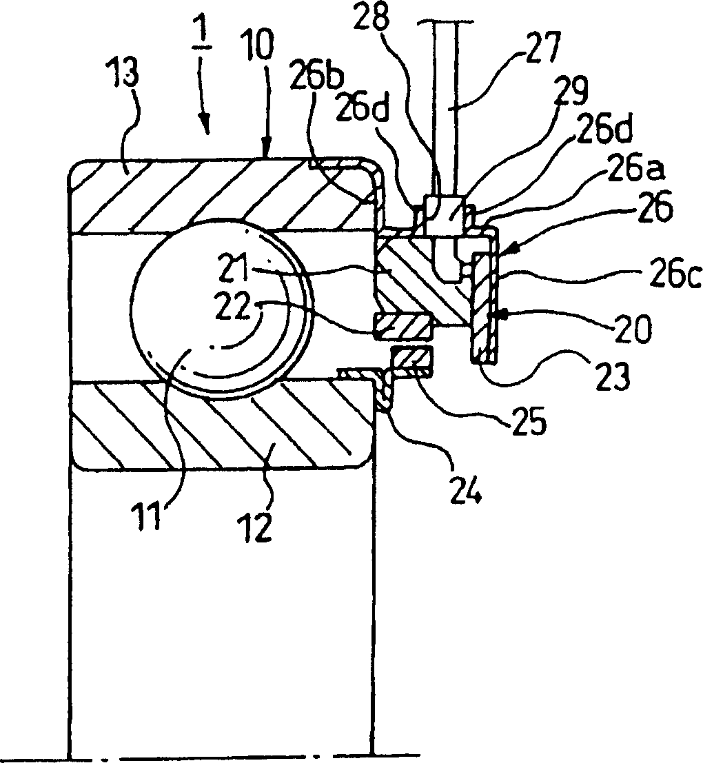
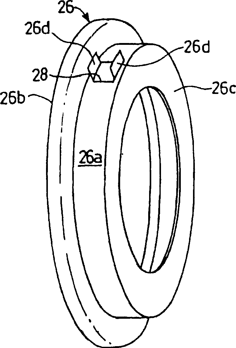
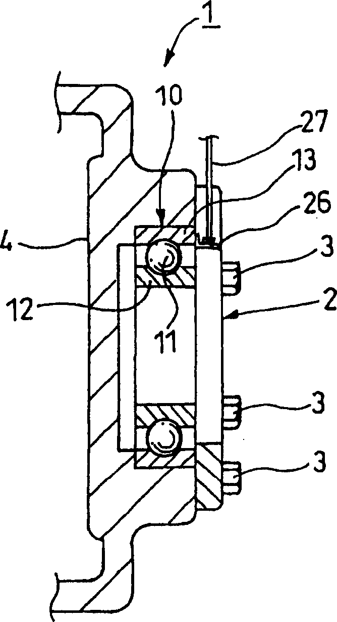
[0113] figure 1 It is a sectional view of main parts showing the first embodiment of the sensor-equipped bearing device of the present invention. figure 2 yes means figure 1 Perspective view of the sensor housing with sensor bearing assembly. image 3 yes means figure 1 The sectional view of the main part of the state where the bearing device with sensor is fixed on the bearing housing; Figure 4 yes image 3 right side view of Figure 5 yes means image 3 Diagram of the pressing part of the bearing unit with sensor.

[0114] Such as figure 1 As shown, the sensored bearing device 1 has a rolling bearing 10 . The rolling bearing 10 has an inner ring 12 as a rotating side ring, an outer ring 13 as a fixed side ring, and a plurality of rolling elements 11 rotatably interposed between the inner ring 12 and the outer ring 13 . The plurality of rolling elements 11 are held at equal intervals in the circumferential direction by cages not shown.

[0115] In addition, th...

no. 2 approach

[0134] Image 6 It is a perspective view for explaining the second embodiment of the sensor-equipped bearing device of the present invention. In addition, in the embodiment described below, the same code|symbol or equivalent code|symbol etc. is attached|subjected to the member etc. which have the structure and function equivalent to what already demonstrated, and description is simplified or omitted.

[0135] In the present embodiment, the protruding portion 31 of the sensor cover 30 is bent so as to protrude in the radial direction by forming a cutout portion of a part of the sensor cover 30 to form a single-leaf hinged door shape.

[0136] Other structures and functions are the same as those of the above-mentioned first embodiment.

no. 3 approach

[0138] Figure 7 It is a perspective view showing the sensor cover of the rolling bearing of the sensor-equipped bearing device according to the third embodiment of the present invention.

[0139] In the present embodiment, the protruding portion 41 of the sensor cover 40 is formed by bending a part of the sensor cover 40 to protrude in the radial direction toward the side (the side surface portion 40 c ) axially opposite to that of the second embodiment to form a single-leaf hinge. door shape.

[0140] Other structures and functions are the same as those of the above-mentioned first embodiment and second embodiment.


PUM


Abstract

A bearing device with a sensor and a rolling bearing with a sensor, which are used in mobile bodies such as automobiles and railway vehicles, or equipment machinery, working machinery, etc., which have: a sensor capable of detecting the state of the rolling bearing, and the sensor is housed inside and fixed on a fixed side sleeve The ring-shaped sensor cover on the ring, the ring-shaped pressing member fixed on the bearing shell or the shaft arranged on the radially outer side of the sensor cover, an opening is provided at a predetermined position of the sensor cover, and a pressure point is provided on the periphery of the opening. The protruding part protruding from the side of the pressing part forms a notch part into which the protruding part is inserted on the pressing part, and the notch part fits with the protruding part.

Description

technical field [0001] The present invention relates to a sensor-equipped bearing device and a sensor-equipped rolling bearing used for mobile bodies such as automobiles and railway vehicles, equipment machinery, and working machines. Phase sensor bearing units and sensor rolling bearings. Background technique [0002] For example, anti-lock braking systems (ABC) and traction control systems (TCS) are widely used in automobiles in recent years. Such controls must accurately detect the rotation speed of the wheels. For this purpose, the rotational speed (number of rotations) of a rolling bearing that rotatably supports the wheel with respect to the suspension is detected. [0003] When detecting the rotational speed (number of revolutions) of a rolling bearing, a sensor-equipped rolling bearing in which a rotation sensor is installed close to the bearing is often used. That is, in a rolling bearing with a sensor, a plurality of cylindrical magnets formed with alternating ma...

Claims


Application Information

Patent Timeline
IPC IPC(8): F16C41/00G01P3/487
Inventor 青木护坂谷郁纪渡部将充
Owner NSK LTD
Why Eureka
Try Eureka