Transformer for producing high electrical currents

Active Publication Date: 2006-03-14
MAGNET PHYSIK DR STEINGROEVER
View PDF7 Cites 6 Cited by
  • Summary
  • Abstract
  • Description
  • Claims
  • Application Information

AI Technical Summary

Problems solved by technology

Such transformers with helically wound primary coils are mechanically very expensive to make.
In addition, with these transformers, the high mechanical forces occurring with high currents between the primary and second coils are not compensated.
Such a return from the center of the coil produces necessary air gaps, which lead to a minimal coil tightne

Method used


Image

  • Transformer for producing high electrical currents
  • Transformer for producing high electrical currents
  • Transformer for producing high electrical currents

Examples


Embodiment Construction

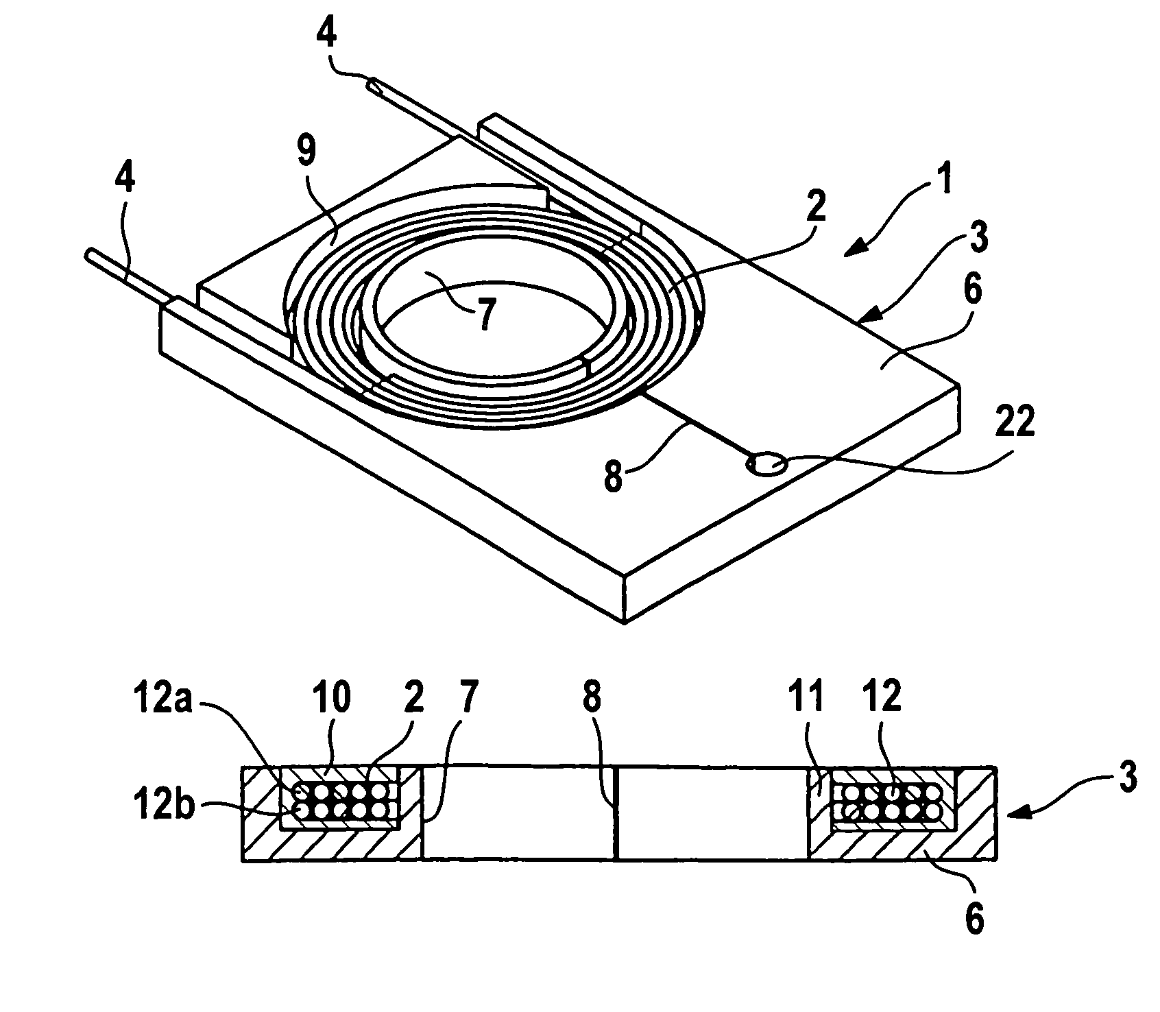
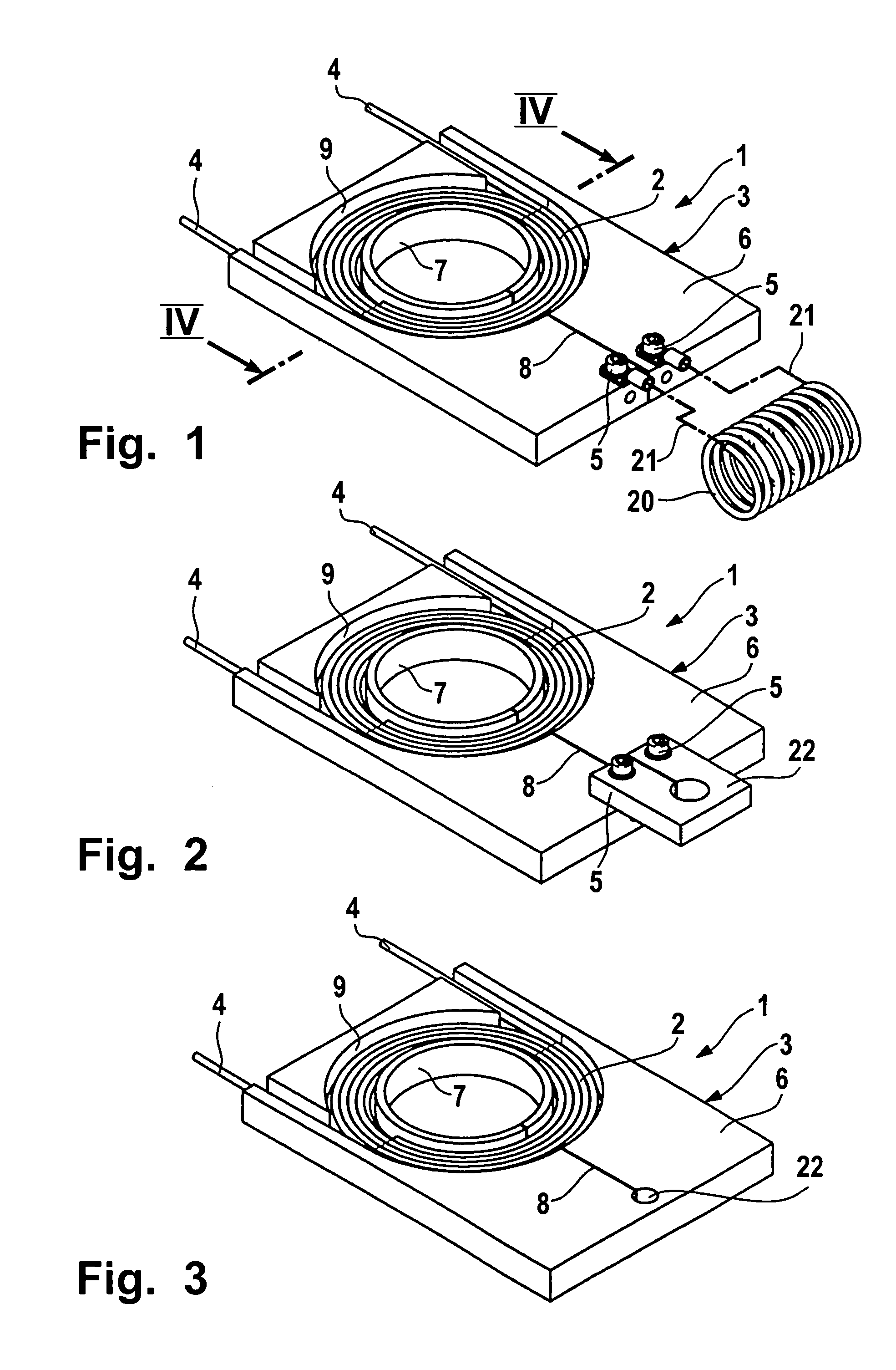
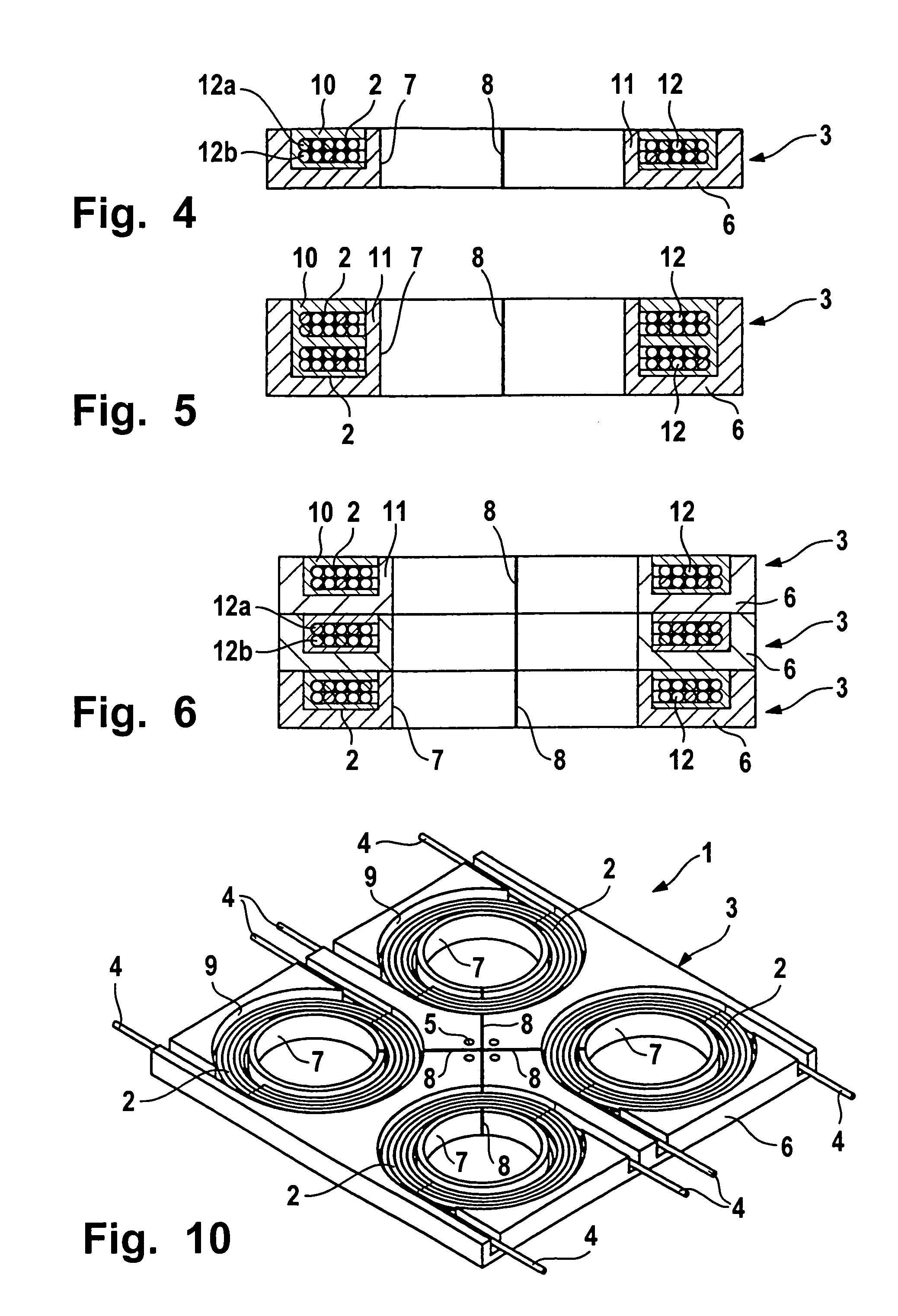
[0027]The transformer 1 shown in various embodiments serves to produce high electrical currents. In particular, it is suited for transformation of high alternating currents as well as power pulse currents for producing magnetic fields in magnetizing technology for magnetizing magnets and magnetic systems, as well as in conversion technology for forming electrically conductive materials by means of magnetic fields. The transformer 1, in its simplest embodiments, comprises at least one primary coil 2 and at least one secondary part 3, which are connected with electrical terminals or bus bars 4 and 5.

[0028]As shown in FIGS. 1 through 4, the secondary part 3 of the transformer comprises at least one electrically conductive plate 6, in which at least one cut-out 7 penetrating the plate 6 is located. On the plate 6, in addition, a slit 8 originating from the cut-out 7 is provided, which separates the plate 6 on one side of the cut-out into two parts and which produces the necessary bus ba...


PUM


Abstract

A transformer (1) serves to produce high electrical currents, in particular, for transforming high alternating and power pulse currents for producing magnetic fields in magnetic technology for magnetizing magnets and magnetic systems, as well as in conversion technology for forming electrically conductive materials by means of a magnetic field. The transformer has at least one primary coil (2) and at least one secondary part (3), which are connected with bus bars (4, 5). The secondary part (3) of the transformer (1) includes at least one electrically conductive plate (6), in which at least one cut-out penetrating the plate (6) is disposed. At least one slit (8) originating from the cut-out (7) is provided, which separates the plate (6) on one side of each cut-out (7) into two parts and produces the required bus bar (5).

Description

BACKGROUND OF THE INVENTION[0001]The present invention relates to a transformer for producing high electrical currents.[0002]With a transformer known from DE 44 23 992 C2 for production of high electrical impulse currents, which is part of an electromagnetic generator for quick current and magnetic field impulse for production of magnetic fields in conversion technology of electrically conductive materials by means of a magnetic field, the primary coil is coiled as an elongated coil in a spiral on a longitudinally slotted supported tube made from copper or another electrically conductive material, which forms the secondary coil with an iron core and are welded or screwed onto the contact block for the current output to a high current loop on the secondary side of the transformer on both sides of the longitudinal slit. The contact blocks are disposed in the center of the support tube, which is provided on each side of the two contact blocks with this type of primary coil.[0003]With a...

Claims


Application Information

Patent Timeline
IPC IPC(8): H01F27/28H01F13/00H01F30/06H01F38/00
CPCH01F38/00H01F30/06H01F13/003
Inventor STEINGROEVER, DIETRICH
Owner MAGNET PHYSIK DR STEINGROEVER
Why Eureka
Try Eureka