Inflow control device

a control device and inflow technology, applied in the direction of drilling machines and methods, borehole/well accessories, underwater drilling, etc., can solve the problems of reducing affecting the oil production rate, and affecting the recovery rate of wells

Inactive Publication Date: 2009-01-01
SCHLUMBERGER TECH CORP
View PDF49 Cites 112 Cited by
  • Summary
  • Abstract
  • Description
  • Claims
  • Application Information

AI Technical Summary

Benefits of technology

[0010]An inflow control device is coupled to the upstream end of the plurality of sand screen assemblies for controlling the flow of fluid into th

Problems solved by technology

In long horizontal wellbores, water or gas coning has a tendency to develop near the heel of the wellbore, because of the buildup of frictional pressure loss towards the toe in the base pipe.
The total oil recovery from the well may be significantly reduced as coning results in a much lower oil

Method used


Image

  • Inflow control device
  • Inflow control device
  • Inflow control device

Examples


Embodiment Construction

[0016]It will be appreciated that the present invention may take many forms and embodiments. In the following description, some embodiments of the invention are described and numerous details are set forth to provide an understanding of the present invention. Those skilled in the art will appreciate, however, that the present invention may be practiced without those details and that numerous variations and modifications from the described embodiments may be possible. The following description is thus intended to illustrate and not to limit the present invention.

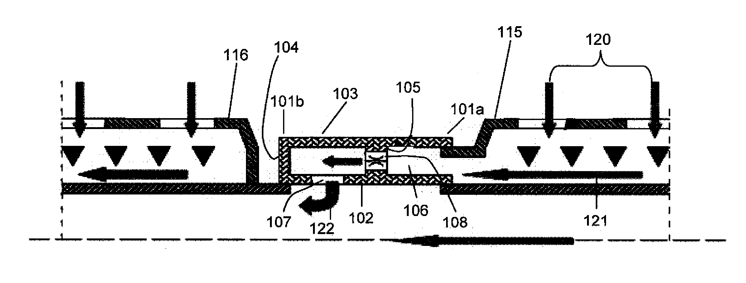
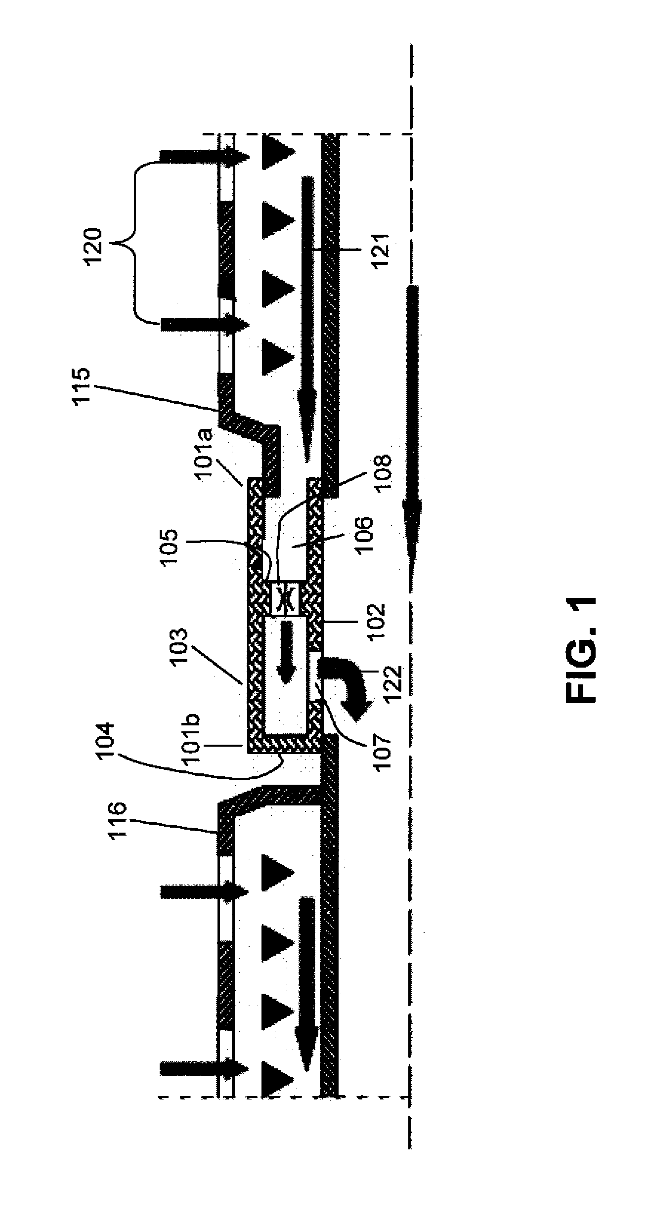
[0017]With reference to FIG. 1, one embodiment of an inflow control device 101 in accordance with the present invention is illustrated. Inflow control device 101 comprises a body with two ends 101a and 101b, and the body comprises inner and outer concentric tubular members 102 and 103, respectively. An annulus 106 is defined between tubular members 102 and 103, with the annulus 106 being closed at end 101b and being open at e...


PUM


Abstract

An inflow control device is disclosed for use in controlling the flow of fluid into a production tubing in a subterranean wellbore. The device is especially adapted for use with sand screen apparatus, but is modular in that it is manufactured separately from the sand screen apparatus. An inflow control device according to the present invention contains an orifice having an opening which is adjustable in size and which is disposed in the device to permit communication of fluid from one end of the body to the other. An inflow control device according to the present invention may be utilized with multiple sand screen assemblies.

Description

BACKGROUND OF THE INVENTION[0001]1. Field of the Invention[0002]The present invention relates to an inflow control device for use in regulating the flow of fluid in a horizontal subterranean wellbore.[0003]2. Description of the Prior Art[0004]In long horizontal wellbores, water or gas coning has a tendency to develop near the heel of the wellbore, because of the buildup of frictional pressure loss towards the toe in the base pipe. The total oil recovery from the well may be significantly reduced as coning results in a much lower oil production rate, which, if allowed to continue, eventually makes the well unprofitable.[0005]Inflow control devices are used to regulate the amount of fluid flowing into the base pipe to avoid coning and to achieve a preferential production of profile. One type of input control device may be deployed via the sand screen assembly. A sand screen joint is usually between 35 and 40 feet long and one inflow control device may be fabricated as part of that joi...

Claims


Application Information

Patent Timeline
IPC IPC(8): E21B43/01
CPCE21B43/08E21B43/32E21B43/12E21B34/06
Inventor HILL, BUNKERFRAKER, MARKYAO, QING
Owner SCHLUMBERGER TECH CORP
Why Eureka
Try Eureka