
Inkjet printing apparatus and printing method

a printing apparatus and printing method technology, applied in the direction of printing, electrical apparatus, spacing mechanisms, etc., can solve the problems of uneven difference, decrease in throughput, and image quality degradation

Inactive Publication Date: 2009-01-01
CANON KK
View PDF13 Cites 14 Cited by
  • Summary
  • Abstract
  • Description
  • Claims
  • Application Information

AI Technical Summary

Benefits of technology

[0048]It is an object of the present invention to provide an inkjet printing apparatus capable of leveling the nozzle use frequency, and canceling application order color unevenness and time difference unevenness without generating any boundary stripe when performing multipass printing, and a printing method therefor.

Problems solved by technology

This generates a stripe and density unevenness in a printed image, degrading the image quality.
However, unlike 1-pass printing, multipass printing increases the number of print scanning operations till the completion of an image, decreasing the throughput.
However, it is known that “application order color unevenness” and “time difference unevenness” occur if bidirectional printing is done by a relatively small number of passes (two to six passes).
Even if multipass printing is executed by increasing the number of passes, application order color unevenness may still occur depending on the ink type and print medium type.
Multipass printing is not the best solution.
It is known that “time difference unevenness” occurs when trying to achieve both a decrease in the number of passes in multipass bidirectional printing and a short reverse time of a carriage for moving the printhead in order to implement high-speed printing.
The image density and color tone become different between adjacent bands at the two ends of a printed image, and density unevenness may occur at the paper feed pitch.
Also, in bidirectional printing by multiple passes larger than two passes, density unevenness may occur because the image density and color tone change owing to the ink landing time difference.
Since the ink discharge order and time difference interval change, this also causes density (color tone) unevenness between bands at the end of an image, as shown in FIG. 9.
Further, the density differs between the right and left ends on the same band, as shown in FIG. 10, and the density difference alternately appears, generating comb-tooth band unevenness.
However, “time difference unevenness” has not been satisfactorily improved yet.
However, this reference does not disclose any measure for multiple passes larger in number than two passes.
However, this technique is one for reducing bleeding at the boundary that occurs every paper feed width, and this reference does not describe the allocation of the printing ratio necessary to reduce time difference unevenness.
“Overflow” degrades the image quality owing to poor ink fixing characteristic.
Owing to this localization, a frequently used nozzle greatly deteriorates over time, shortening the service life of the printhead.

Method used


Image

  • Inkjet printing apparatus and printing method
  • Inkjet printing apparatus and printing method
  • Inkjet printing apparatus and printing method

Examples


first embodiment

[0126]In the first embodiment, printing is done using a combination of masks prepared in a memory in accordance with the position where an image is printed. In the first embodiment, 4-pass printing is executed to complete an image by four scanning operations with cyan (C), magenta (M), yellow (Y), and black (K) inks.

[0127]Each process of 4-pass printing will be described first with reference to FIG. 9. The printhead has a nozzle array (printing element array) of 1,280 nozzles for each color, and the nozzle arrays of the respective colors are juxtaposed.

[0128]In first print scanning 9-001, printing is done as reverse printing by discharging C, M, Y, and K inks in the order named from ¼ nozzles (320 nozzles) at the leading end of the nozzle array. After an image is printed to the right end in FIG. 9, the printhead scanning direction is reversed, and paper is fed by an amount corresponding to a ¼ width (320 pixels) of the nozzle array.

[0129]In second print scanning 9-002, printing is d...

second embodiment

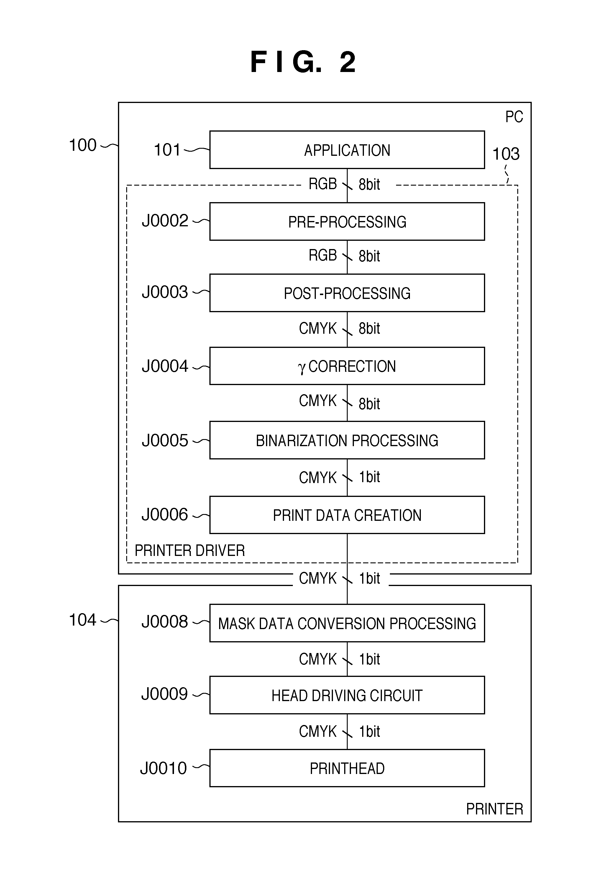
[0146]In the second embodiment, the same apparatus as that in the first embodiment is used to receive multilevel image data from a PC, divide it without converting it, and binarize the divided multilevel data when converting it into print data used for printing by each pass. FIG. 17 is a block diagram showing main data processes till printing in the second embodiment.

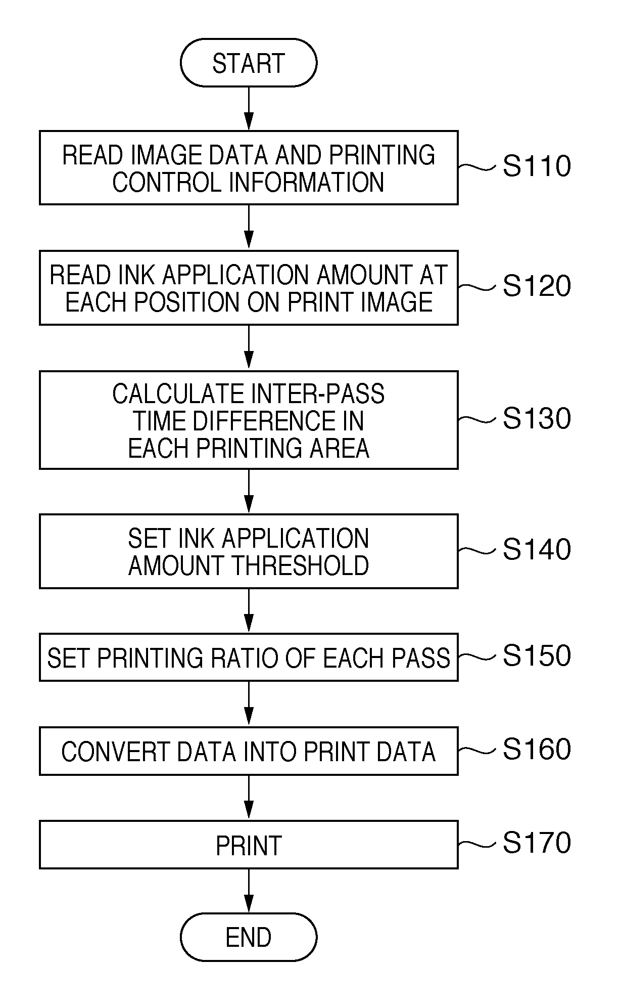
[0147]A printing method according to the second embodiment will be described with reference to the flowchart of FIG. 20.

[0148]Similar to the first embodiment, image data and printing control information are read in step S110. In the second embodiment, however, the image data is not binarized in this step. Steps S120 to S150 are the same as those in the first embodiment.

[0149]In step S160, the multilevel image data read in step S110 is divided into multilevel data for printing by respective passes on the basis of the printing ratios of these passes set in step S150. The divided multilevel image data is converted into bin...

third embodiment

[0151]The third embodiment will describe a case where input of image data from a PC delays or a case where an inter-pass time difference larger than one in normal printing is generated owing to the maintenance of the printhead. For example, after printing starts at equal printing ratios in all print scanning operations on the basis of image data for which no printing ratio allocation need be changed, the printhead retracts to a predetermined position during printing owing to the above-mentioned reason. The present invention is applicable to even this case. The third embodiment will exemplify a case where data transfer from a PC delays because of any reason and a 5-sec standby time is generated after the end of the first print scanning during printing.

[0152]In this case, printing has ended by 25% by the first print scanning. At this time, the remaining 75% of printing is executed by three remaining print scanning operations. The printhead stands still at the right end of the image du...


PUM


Abstract

There is provided an inkjet printing apparatus which prints using a printhead for discharging ink by a plurality of scanning operations of the printhead including forward scanning and reverse scanning in a single area of a print medium. In the inkjet printing apparatus, the ink discharge amount is acquired for each unit area obtained by dividing the end area of the single area in the scanning direction. The acquired ink discharge amount of each unit area is compared with a predetermined threshold. The printing ratios of the plurality of scanning operations are controlled to set the printing ratio of the final scanning operation lower than the average one of the remaining scanning operations in a unit area where the ink discharge amount is larger than the predetermined threshold.

Description

BACKGROUND OF THE INVENTION[0001]1. Field of the Invention[0002]The present invention relates to an inkjet printing apparatus which prints an image with ink containing a color material and a printing method therefor. More particularly, the present invention relates to an inkjet printing apparatus which forms an image by multipass printing by reciprocally scanning a multi-nozzle inkjet printhead (to be also simply referred to as a printhead hereinafter) having an array of nozzles for discharging ink with respect to a print medium, and a printing method therefor.[0003]2. Description of the Related Art[0004]As information processing devices such as a computer have become popular and communication devices have spread upon improvement of the communication environment, an inkjet printing apparatus which prints a digital image using an inkjet printhead is rapidly becoming pervasive as one of printing apparatuses used together with these devices.[0005]A kind of inkjet printing apparatus use...

Claims


Application Information

Patent Timeline
Patent Type & Authority Applications(United States)
IPC IPC(8): B41J29/38
CPCB41J2/2132H04N1/405B41J29/02B41J19/142
Inventor SHIBATA, TSUYOSHIYAMAGUCHI, HIROMITSUWADA, SATOSHIJAHANA, RYOKI
Owner CANON KK
Learn More