Systems and methods for collision avoidance in a multiple RFID interrogator environment

a technology of collision avoidance and interrogator environment, applied in the field of radio frequency identification, can solve the problems of battery price, device size is small, and the manufacture cost is more expensiv

Active Publication Date: 2009-01-15
SMARTRAC TECH FLETCHER INC
View PDF10 Cites 14 Cited by
  • Summary
  • Abstract
  • Description
  • Claims
  • Application Information

AI Technical Summary

Benefits of technology

[0024]According to another aspect, an RFID interrogator comprises a transmit circuit configured to generate transmit data, a receive circuit configured to decode receive data, a collision detection circuit configured to compare the transmit data with the receive data, a processor coupled with the transmit circuit and the receive circuit, the processor configured to execute instructions, and a memory coupled with the processor, the memory configured to store instructions, the instructions configured to cause the processor to enter a quiet state during which the processor prevent the transmit circuit from generating transmit data, select a transmit time after the quiet period during which the interrogator will attempt to transmit data via the transmit circuit, cause an instruction to be transmit an instruction during the selected transmit time indicting the beginning of a session when the receiver does not detect data on its receive path prior to the select transmit time, return to the quiet state when the collision detection circuit detects that the receive path does not match the transmit path after the instruction is transmitted, and allow the interrogator to complete the session when the collision detection circuit determines that the receive path matches the transmit path after the instruction is transmitted.

Problems solved by technology

The lack of an onboard power supply means that the device can be quite small.
In turn, active tags are generally bigger, caused by battery volume, and more expensive to manufacture, caused by battery price.
Semi-passive tags are similar to active tags in that they have their own power source, but the battery only powers the microchip and does not power the broadcasting of a signal.
The collision problem can also affect the readers, or interrogators, i.e., it is possible in certain environments for multiple interrogators to transmit at the same time, which can create communication problems within the system.
Thus, multiple and / or dense reader environments can produce communication problems due to two or more readers transmitting at the same time.

Method used


Image

  • Systems and methods for collision avoidance in a multiple RFID interrogator environment
  • Systems and methods for collision avoidance in a multiple RFID interrogator environment
  • Systems and methods for collision avoidance in a multiple RFID interrogator environment

Examples


Embodiment Construction

.”

BRIEF DESCRIPTION OF THE DRAWINGS

[0026]Features, aspects, and embodiments are described in conjunction with the attached drawings, in which:

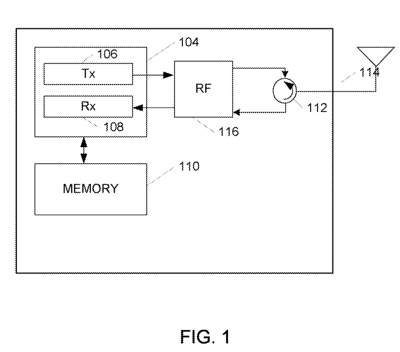
[0027]FIG. 1 is a diagram illustrating an example RFID interrogator in accordance with one embodiment;

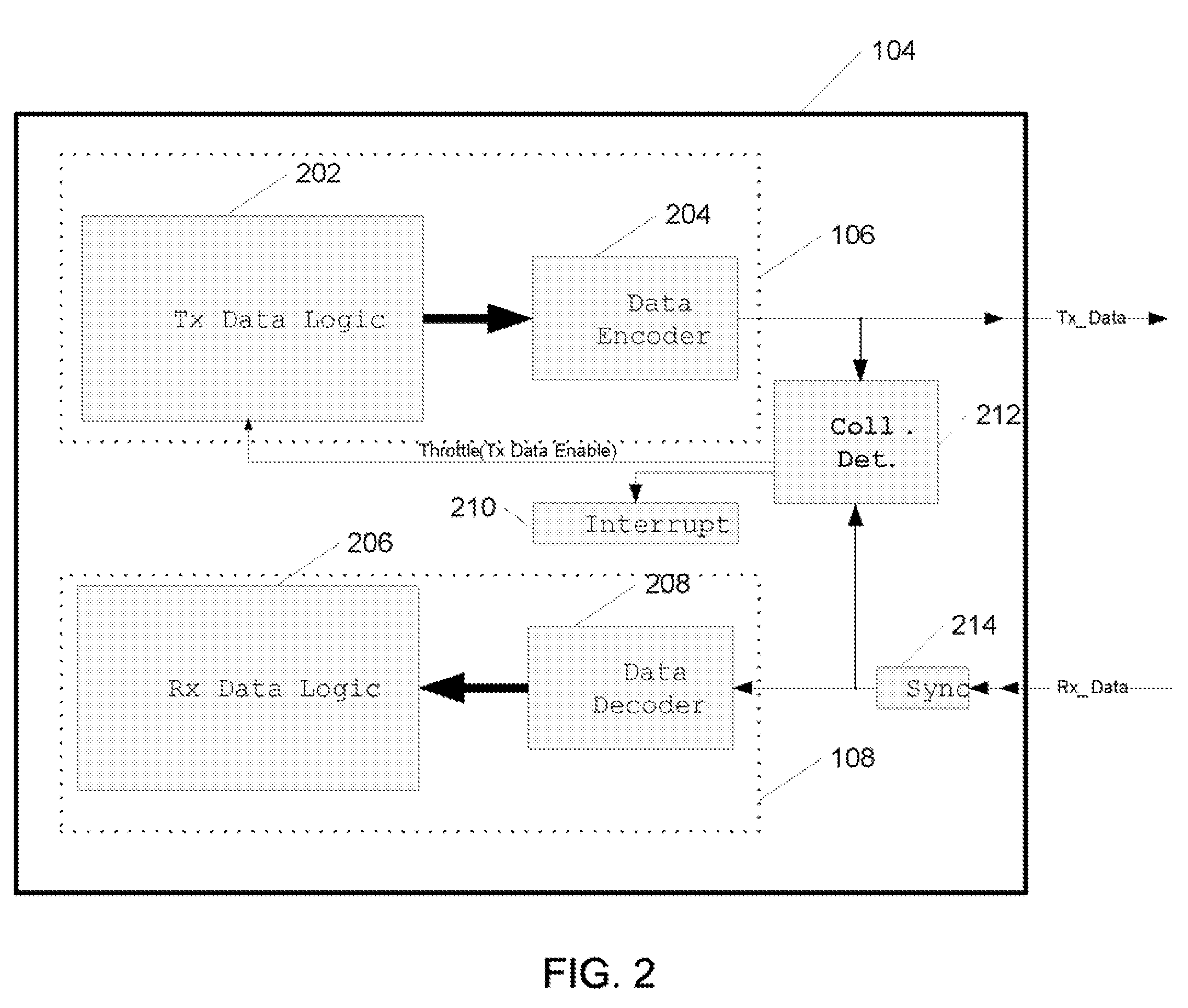
[0028]FIG. 2 is a diagram illustrating an baseband processing circuit that can be included in the interrogator of FIG. 1;

[0029]FIG. 3 is a flow chart illustrating an example process for collision avoidance that can be implemented when the interrogator of FIG. 1 is operating in a multi-interrogator environment in accordance with one embodiment;

[0030]FIG. 4 is a session diagram illustrating an example session that can be implemented in accordance with the process illustrated in FIG. 3; and

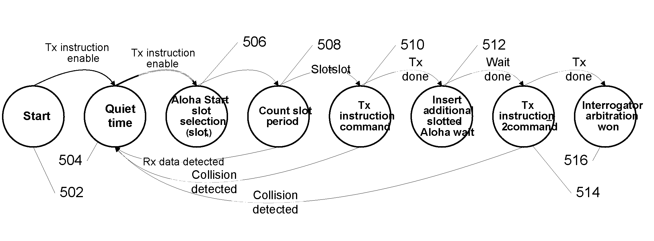
[0031]FIG. 5 is a state diagram illustrating one example implementation of the process illustrated in FIG. 3.

DETAILED DESCRIPTION

[0032]The basis of the collision avoidance discussed with respect to the embodiments described below can comprise three main aspec...


PUM


Abstract

A method for collision avoidance in a multi-reader environment comprising a plurality of Radio Frequency Identification (RFID) interrogators, the method comprises each of the plurality of interrogators entering a quiet state during which none of the interrogators transmits, each of the plurality of interrogators selecting a transmit time after the quiet period during which each of the interrogator will attempt to transmit, each of the plurality of interrogators monitoring their associated receive path, an interrogator of the plurality of interrogators transmitting an instruction during its selected transmit time indicating the beginning of a session when the interrogator does not detect data on its receive path prior to its select transmit time, the interrogator comparing its receive path to its transmit path when it transmits the instruction, the interrogator returning to the quiet state when the receive path does not match the transmit path, and the interrogator completing the session when the receive path matches the transmit path.

Description

RELATED APPLICATIONS INFORMATION[0001]This application claims the benefit under 35 U.S.C. 119(e) of U.S. Provisional Patent Application Ser. No. 60 / 947,110, filed Jun. 29, 2007, and entitled “Collision Avoidance in Multiple RFID Reader Environment, which is incorporated herein by reference in its entirety as if set forth in full.BACKGROUND[0002]1. Technical Field[0003]The embodiments described herein relate generally to radio Frequency Identification (RFID), and more particularly to RFID protocols and methods that can be used to avoid collisions among a plurality of interrogators in a single environment.[0004]2. Related Art[0005]Radio-frequency identification (RFID) is an automatic identification method, relying on storing and remotely retrieving data using devices called RFID tags or transponders. An RFID tag is an object that can be applied to or incorporated into a product, animal, or person for the purpose of identification using radio waves. The data is retrieved from the RFID ...

Claims


Application Information

Patent Timeline
Patent Type & Authority Applications(United States)
IPC IPC(8): H04Q5/22G08B13/14
CPCG06K7/0008H04W74/085G06K7/10356G06K7/10019
Inventor GREEFKES, KIRK
Owner SMARTRAC TECH FLETCHER INC
Why Eureka
Try Eureka