Wire protecting member and wire harness
- Summary
- Abstract
- Description
- Claims
- Application Information
AI Technical Summary
Benefits of technology
Problems solved by technology
Method used
Image

Examples
embodiment 1
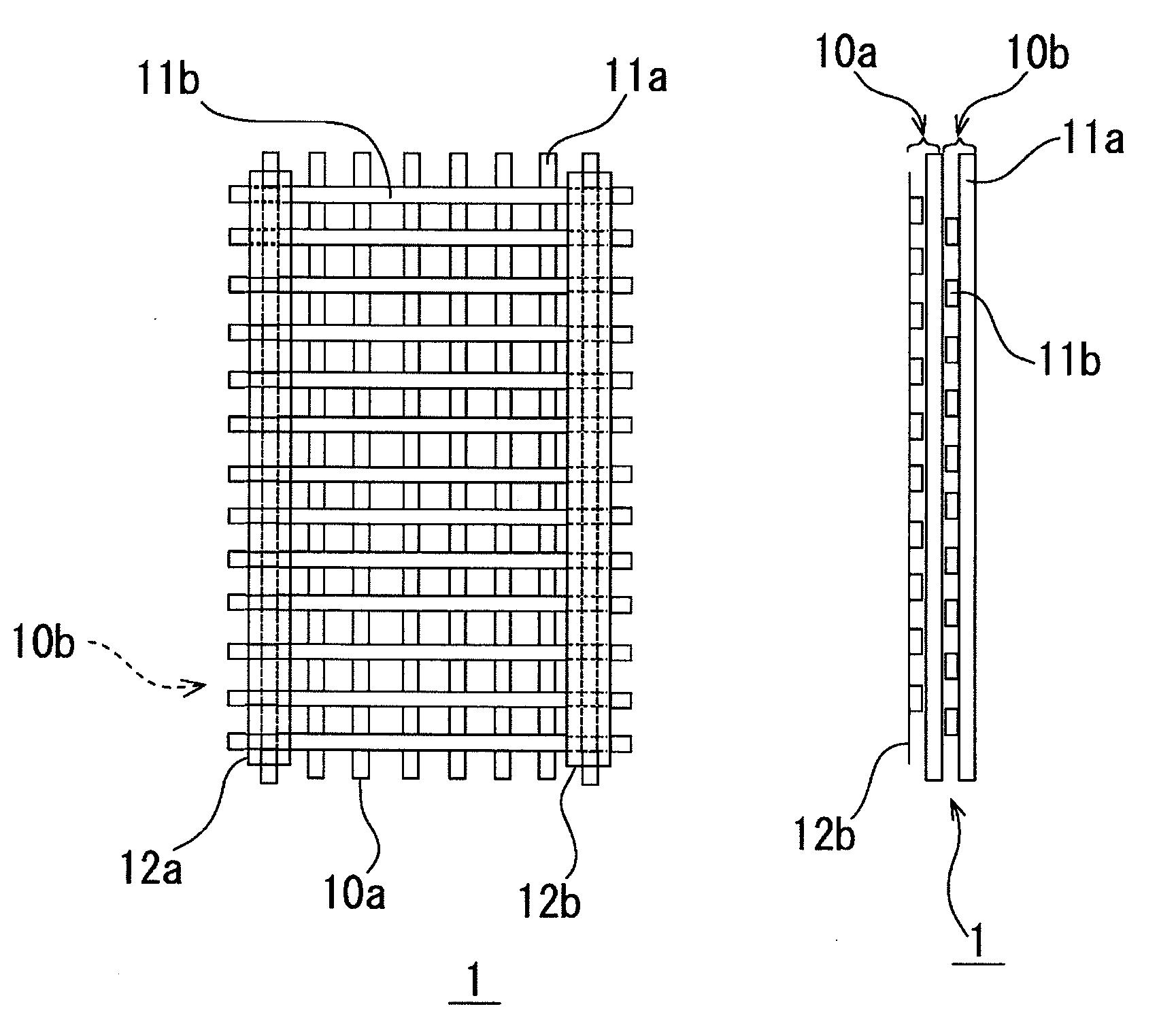
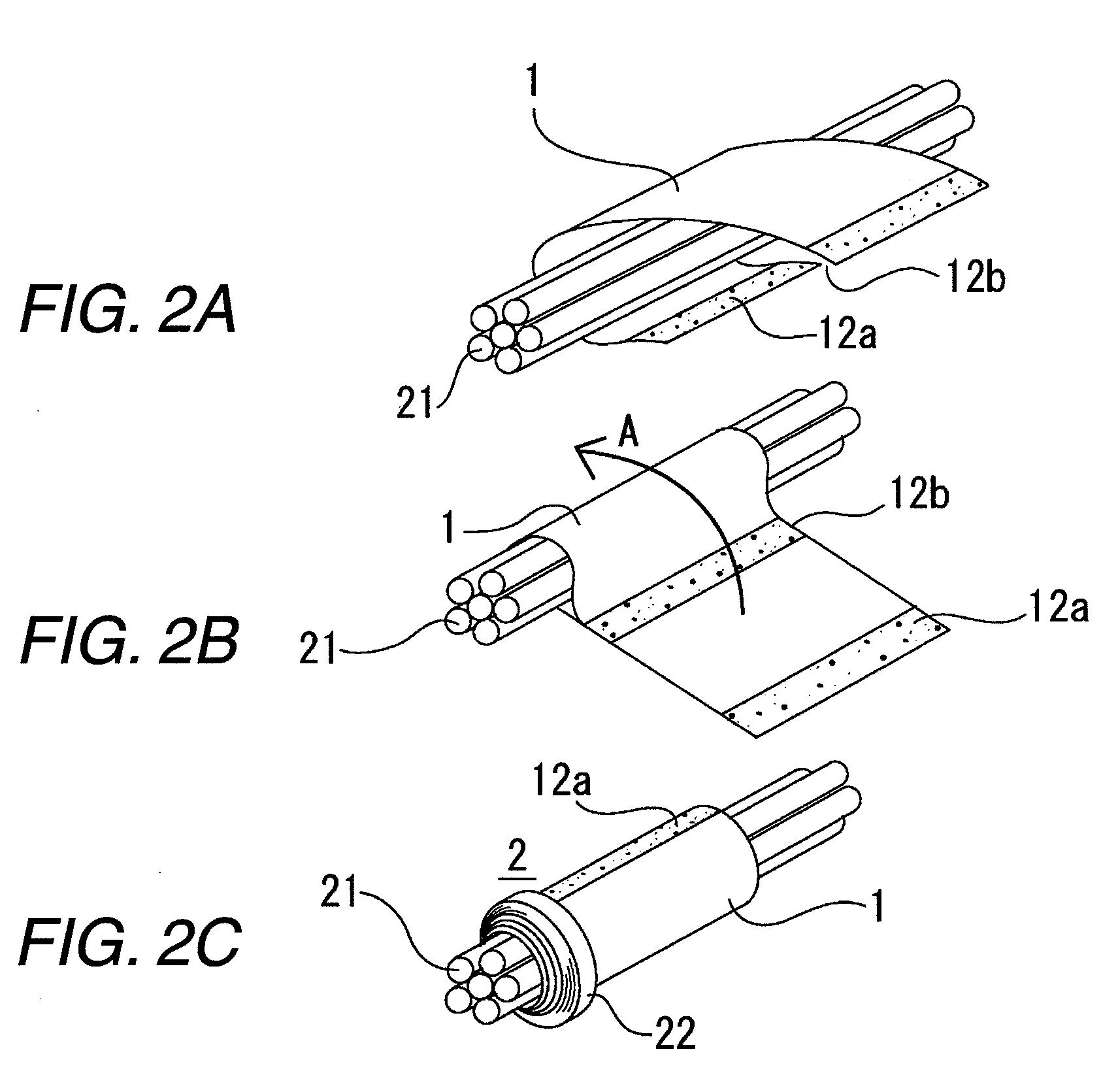
[0024]FIGS. 1A and 1B are a front-elevational view and a right side-elevational view of a wire protecting member 1, respectively. This wire protecting member 1 is formed by two meshes 10 (10a, 10b) of reinforced fibers stacked together.
[0025]With respect to the stacking of the two meshes, the stacking is effected in such a manner that longitudinal split fibers 11a in the first mesh 10a are disposed parallel to longitudinal split fibers 11a in the second mesh 10b. With respect to fiber directions of lateral split fibers 11b, also, the stacking is made similarly. With this construction, there is formed the wire protecting member 1 having a protecting performance as a sheath of a wire harness.
[0026]Each mesh 10 is formed by a large number of longitudinal split fibers 11a (comprising reinforced fibers) and a large number of lateral split fibers 11b (comprising reinforced fibers) which intersect each other and are thermally fused together. For example, an oriented reinforced polyolefin i...
embodiment 2
[0035]A wire protecting member 1 according to an embodiment 2 is an example in which with respect to the stacked structure of the plurality of reinforced fiber meshes 10 of the embodiment 1, the stacking is effected such that a fiber direction of longitudinal split fibers 11a in a first mesh 10a and a fiber direction of longitudinal split fibers 11a in a second mesh 10b are not parallel to each other but are different from each other (for example, oblique relative to each other). The other constituent portions are the same as those of the embodiment 1, and therefore will be designated by identical reference numerals, respectively, and detailed description thereof will be omitted.
[0036]FIG. 4 shows the directions of the split fibers of the two meshes 10a, 10b forming the wire protecting member 1 as well as the positional relation of a wire group 21 on which this wire protecting member 1 is to be wound. It shows the case where the fiber direction of the longitudinal split fibers 11a o...
embodiment 3
[0040]A wire protecting member 1 according to an embodiment 3 is an example which is formed by one mesh 10 in contrast with the stacked structure of the plurality of reinforced fiber meshes 10 of the embodiment 1. The other constituent portions are the same as those of the embodiment 1, and therefore will be designated by identical reference numerals, respectively, and detailed description thereof will be omitted.
[0041]FIG. 6 shows the directions of split fibers of the mesh 10 forming the wire protecting member 1 as well as the positional relation of a wire group 21 on which this wire protecting member 1 is to be wound. It shows the case where the direction of the longitudinal split fibers 11a of the mesh 10 is perpendicular to an axial direction of a wire harness 2 on which the wire protecting member is to be wound.
[0042]The wire protecting member 1 is formed by this mesh 10, and this wire protecting member 1 is wound relative to the wire group 21 as described above, thereby formin...
PUM
| Property | Measurement | Unit |
|---|---|---|
| Mesh size | aaaaa | aaaaa |
| Mesh size | aaaaa | aaaaa |
Abstract
Description
Claims
Application Information
 - R&D Engineer
- R&D Manager
- IP Professional
- Industry Leading Data Capabilities
- Powerful AI technology
- Patent DNA Extraction
Browse by: Latest US Patents, China's latest patents, Technical Efficacy Thesaurus, Application Domain, Technology Topic.
© 2024 PatSnap. All rights reserved.Legal|Privacy policy|Modern Slavery Act Transparency Statement|Sitemap