Tensioner lever

Active Publication Date: 2009-02-05
TSUBAKIMOTO CHAIN CO
View PDF11 Cites 12 Cited by
  • Summary
  • Abstract
  • Description
  • Claims
  • Application Information

AI Technical Summary

Benefits of technology

[0006]An object of this invention, therefore, is to solve the above-mentioned problems, and to provide a tensioner lever which suppresses galling, seizing, asymmetric wear, and friction loss in a pivoted tensioner lever. These objects are addressed by utilizing engine oil more efficiently to lubricate the tensioner lever.

Problems solved by technology

However, when the boss 530 of the conventional tensioner lever is in contact with an inner wall of an engine E as shown in FIG. 7, or in contact with the flange Sf of a shoulder bolt SB, as shown in FIG. 8, oil can flow into the space between the bolt and the inner surface of the boss from only one end of the boss, and there is insufficient room for oil to flow into this space from the opposite end of the boss.
As a result, galling, seizing, and asymmetric, i.e., one-sided, wear of the mounting bolt and the interior of the boss, can occur due to insufficient lubrication, and early failure of the tensioner lever can occur.

Method used


Image

  • Tensioner lever
  • Tensioner lever
  • Tensioner lever

Examples


Embodiment Construction

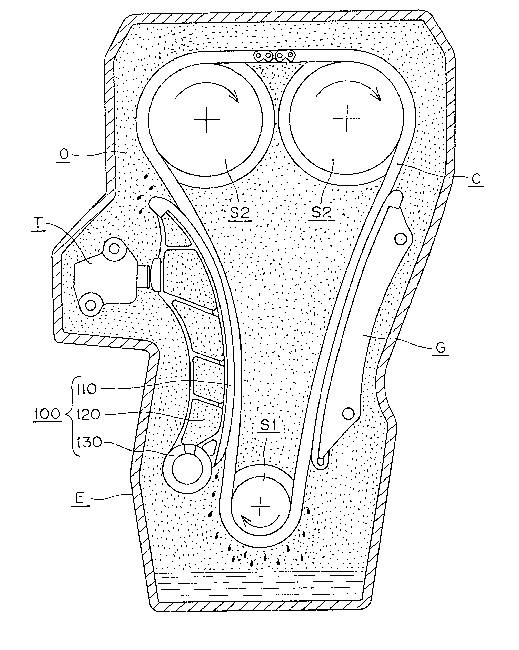
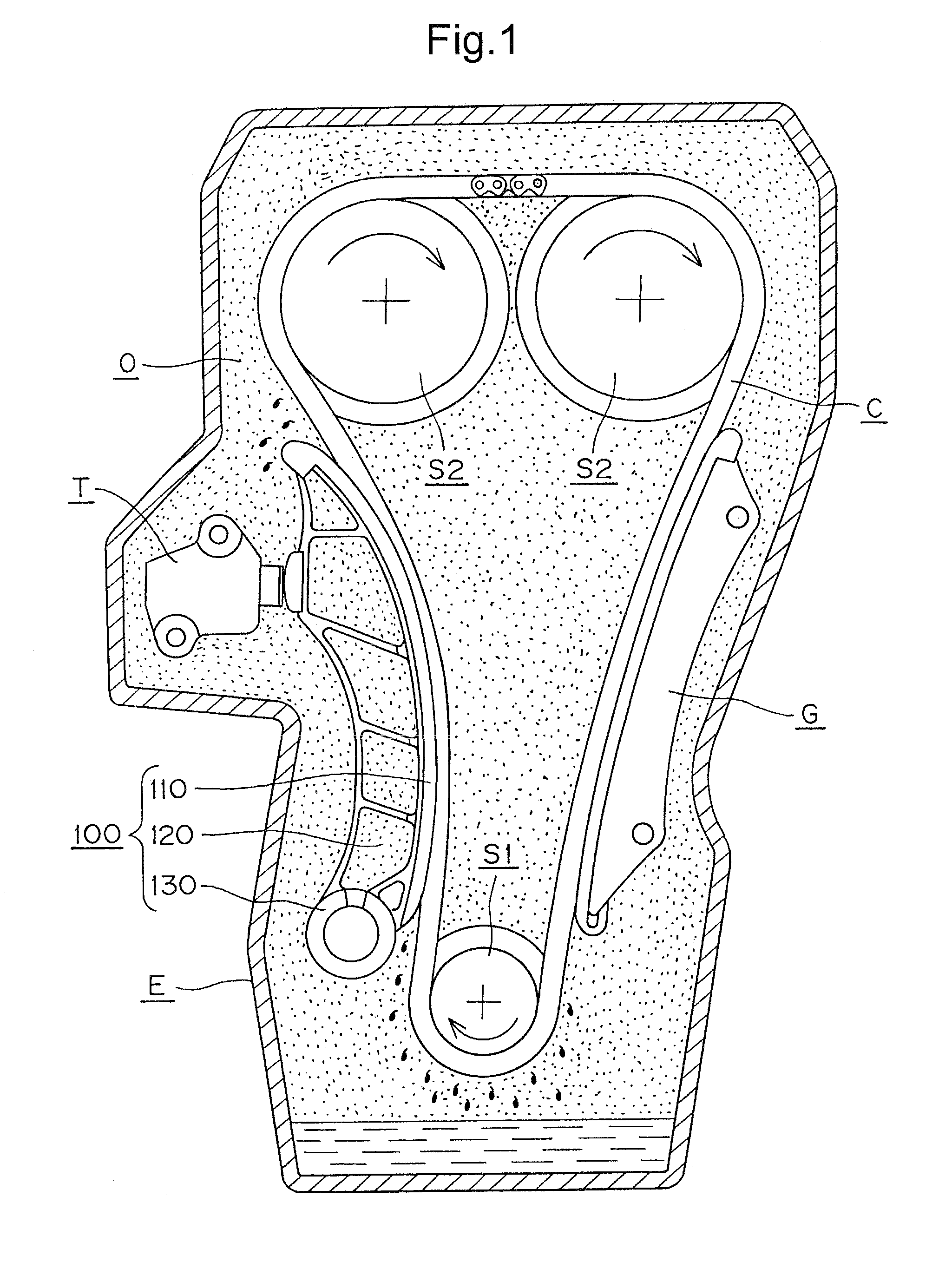
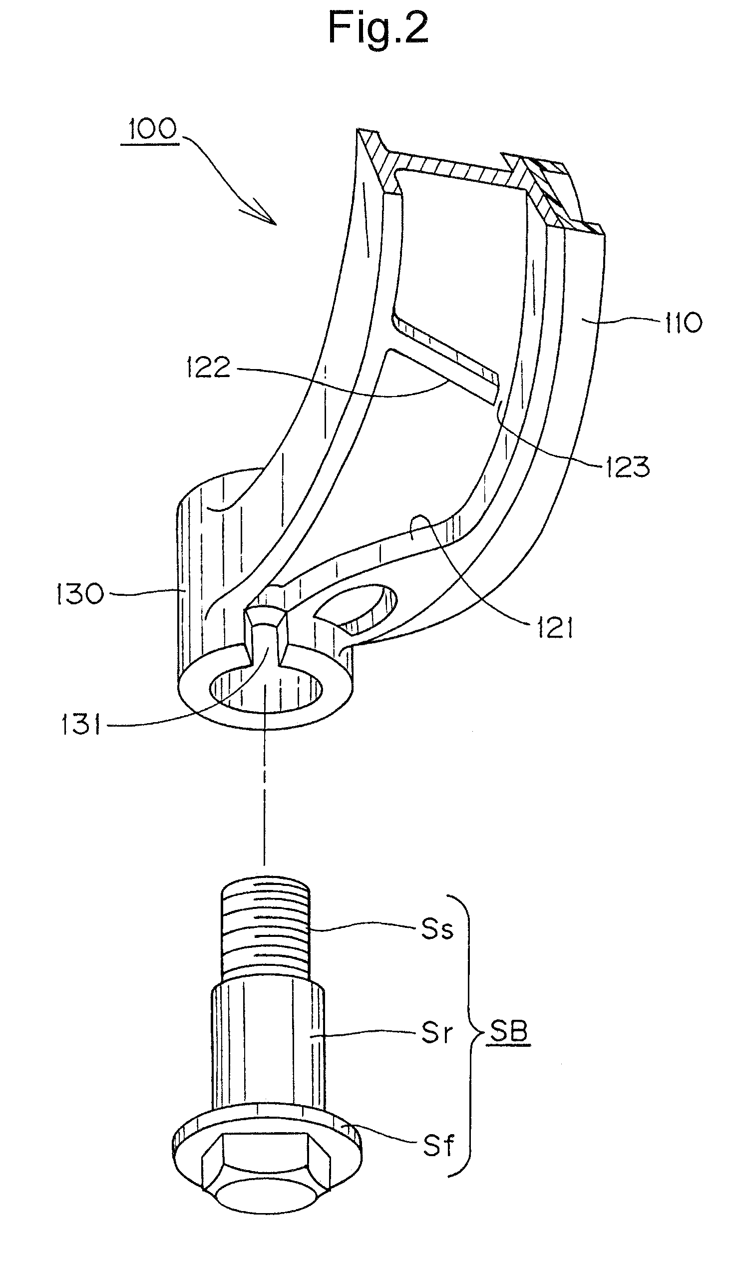
[0026]The tensioner lever in accordance with the invention is characterized by an oil guiding groove, extending from the outer circumferential surface to the inner circumferential surface of the lever-mounting boss, for guiding engine oil adhering to the lever body to the region between the shaft portion of a shoulder bolt on which the lever is pivotally mounted and the inner surface of the through hole in the mounting boss. The groove provides for more effective utilization of engine oil in lubricating the lever. Galling, seizing, asymmetric wear, and friction loss are suppressed, improved endurance is exhibited, and the lever maintains proper tension in a transmission chain by smoothly following changes in chain tension in cooperation with a tensioner.

[0027]The lever of the invention can be embodied in various forms. For example, the lever can comprise a shoe and a lever body composed of different materials, e.g., a synthetic resin and metal, respectively. Alternatively, the lever...


PUM


Abstract

In a pivoted tensioner lever extending upward from a pivot axis, both ends of boss through which a pivot shaft extends are provided with funnel-shaped grooves that guide oil adhering to the lever body into a region between the shaft and the inside of the boss. Oil guiding walls, continuous with the boss, and downwardly sloping reinforcing ribs with oil passages formed at their lower ends, increase flow of oil adhering to the lever body to the region between the shaft and the inside of the boss

Description

CROSS-REFERENCE TO RELATED APPLICATION[0001]This application claims priority on the basis of Japanese patent application 2007-200136, filed Jul. 31, 2007. The disclosure of Japanese application 2007-200136 is hereby incorporated by reference.FIELD OF THE INVENTION[0002]This invention relates to a tensioner lever, for use in a chain transmission in an automobile engine or the like. The chain transmission transmits power from a driving sprocket to a driven sprocket, and the tensioner lever cooperates with a tensioner to maintain appropriate tension in the chain. The invention relates more specifically to a pivoted tensioner lever which extends upward from its pivot axis.BACKGROUND OF THE INVENTION[0003]Pivoted tensioner levers have been widely used for maintaining tension in transmission chains used as timing chains in internal combustion engines. These levers have shoes that are in sliding contact with a portion of the transmission chain, and are typically pivoted on shoulder bolts s...

Claims


Application Information

Patent Timeline
IPC IPC(8): F16H7/08
CPCF16H2007/0872F16H7/18F16H7/08
Inventor HIRAYAMA, MANABUSAITOH, TOYONAGA
Owner TSUBAKIMOTO CHAIN CO
Why Eureka
Try Eureka