Food cutting device

a technology of food cutting device and cutting blade, which is applied in the direction of manufacturing tools, portable power-driven tools, grain treatment, etc., can solve the problem that the performance of such cutting devices is not satisfactory

Inactive Publication Date: 2009-02-19
SO
View PDF4 Cites 39 Cited by
  • Summary
  • Abstract
  • Description
  • Claims
  • Application Information

AI Technical Summary

Problems solved by technology

The performance of such food cutting devices is not found to be satisfactory, especially concerning how small they can cut food into and how quickly they can do so.

Method used


Image

  • Food cutting device
  • Food cutting device
  • Food cutting device

Examples


Embodiment Construction

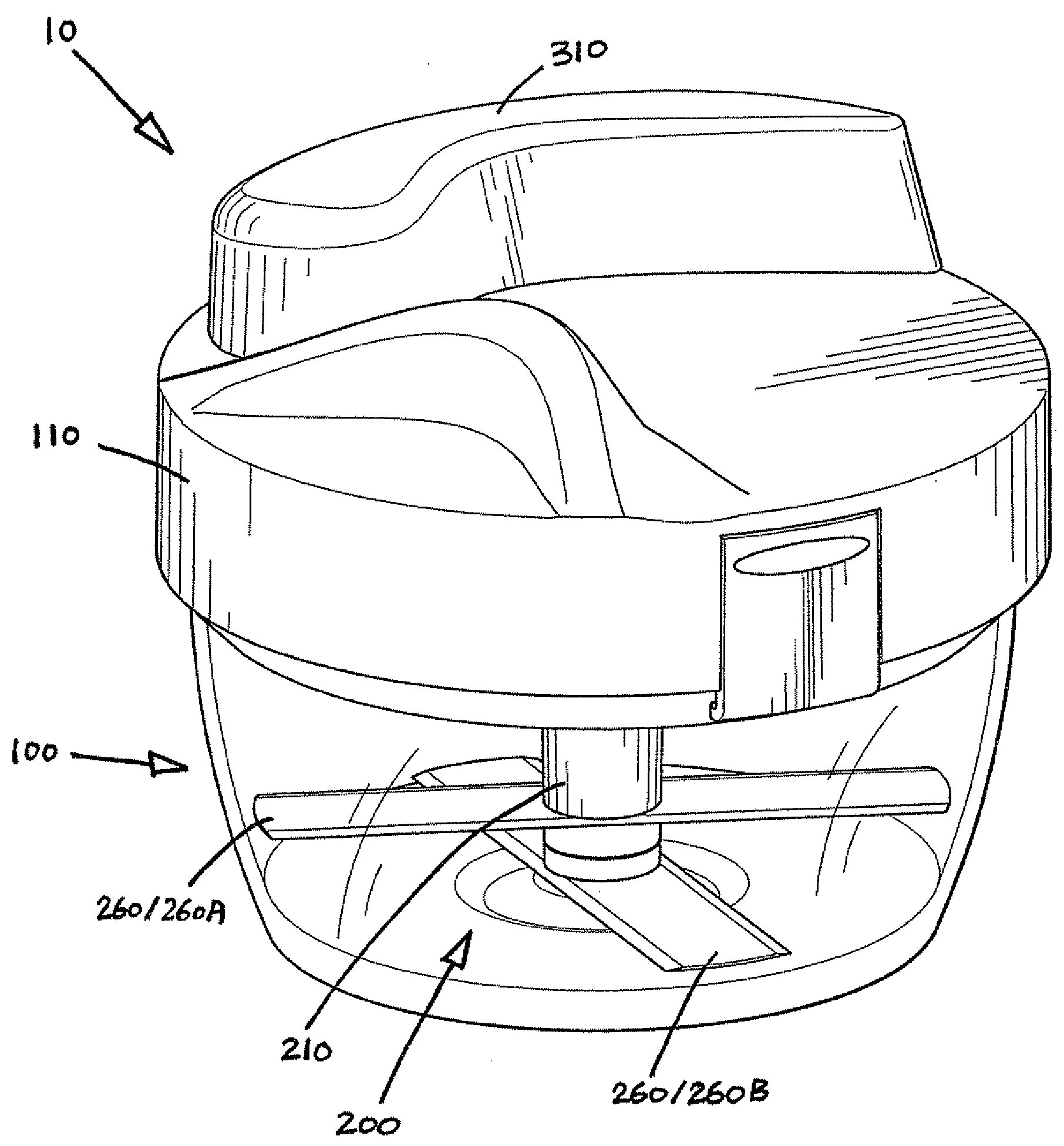
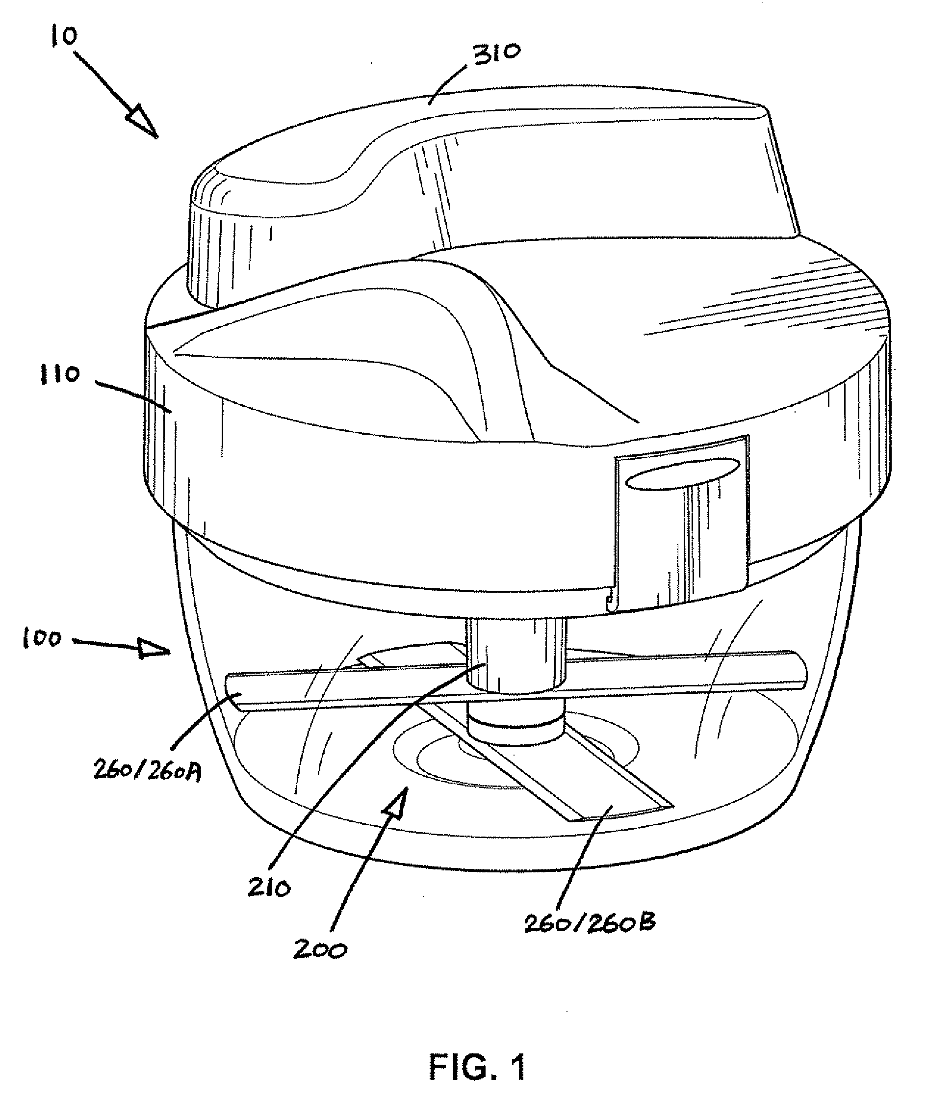
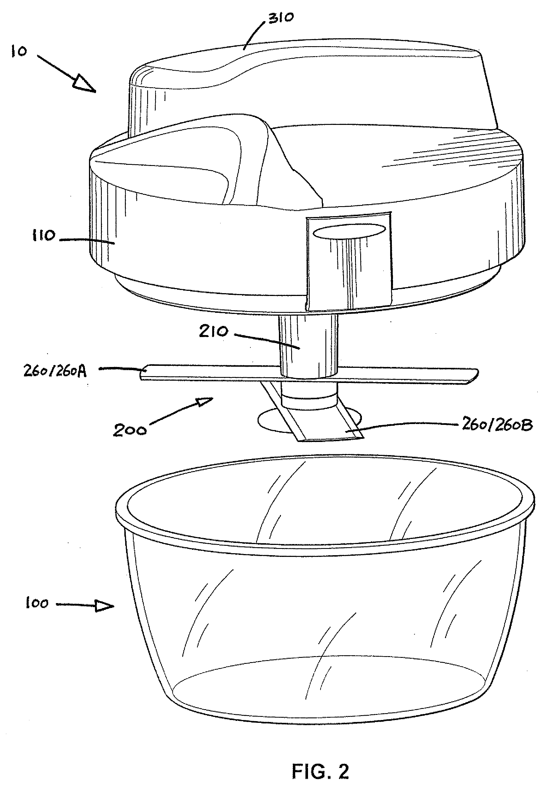
[0046]Referring to FIGS. 1 to 13 of the drawings, there is shown a food cutting device in the form of a food chopper embodying the invention, which has a body taking the form of a plastic bowl 100 with a circular lid 110 and includes a chopper unit 200 in the bowl 100. The chopper unit 200 is a removable unit implemented by a pair of straight metal cutting blades 260 that are supported horizontally at mid-length on a vertical plastic shaft 210. Each of the cutting blades 260 has a pair of opposite limbs that are symmetrical and are equi-angularly spaced.

[0047]Inside the bowl 100, the shaft 210 is arranged to be turned about its own axis X to thereby rotate the cutting blades 260 about the axis X for cutting food items, such as garlic cloves or carrot cubes, held in the bowl 100. The lid 110 is hollow and houses a drive mechanism 300 for driving the chopper unit 200 i.e. rotating the cutting blades 260.

[0048]As best shown in FIG. 8, the shaft 210 has a composite structure which is fo...


PUM


Abstract

A food cutting device has a bowl, two cutting blades supported in the bowl for rotation relative to each other, and a drive mechanism supported by the bowl for rotating the cutting blades to cut food in the bowl. The cutting blades are rotatable in opposite directions relative to each other to perform a scissors-like cutting action.

Description

[0001]The present invention relates to a manually operated food cutting device that operates with a rotary action.BACKGROUND OF INVENTION[0002]Food cutting devices of the type concerned, such as food choppers, find common use in kitchens for cutting food items such as garlic cloves and carrot cubes into much smaller pieces. These food cutting devices are hand-operated utensils, especially those for domestic use.[0003]In a typical construction, such food cutting devices has a container in which a rotary cutter unit is provided for cutting food in the container and includes a manually-operated drive mechanism atop or on one side for driving the cutter unit. The drive mechanism usually incorporates a handle on a crank for turning by a user.[0004]The performance of such food cutting devices is not found to be satisfactory, especially concerning how small they can cut food into and how quickly they can do so.[0005]The invention seeks to obviate or at least alleviate one or more of such p...

Claims


Application Information

Patent Timeline
Patent Type & Authority Applications(United States)
IPC IPC(8): A47J43/28B25F1/00B65D85/00
CPCA47J43/044A47J43/082A47J43/0705
Inventor SO, KWOK KUENWAN, YIU CHUNGWONG, CLIVE KOON YIN
Owner SO
Why Eureka
Try Eureka