
System for a Greaseless Switch Assembly

a switch assembly and greaseless technology, applied in railway signalling, transportation and packaging, roads, etc., can solve the problems of switch machine locking up, not applicable to the operation of switch points of interconnected types

Inactive Publication Date: 2009-02-19
GENERAL ELECTRIC CO
View PDF20 Cites 4 Cited by
  • Summary
  • Abstract
  • Description
  • Claims
  • Application Information

AI Technical Summary

Problems solved by technology

The device described in that patent operates switch points which are independent, or disconnected, from each other, and it is not applicable to the problem of operating switch points of the interconnected type, i.e. of switch points connected to each other by transverse bars.
In addition, a more paramount problem that results is due to the thermal expansion of the tongue, or the part that is moved to set the track of the switch.
This lateral reactive force can cause premature failure of the seal and binding of the operating rod relative to the housing, which can cause the switch machine to lock up.

Method used


Image

  • System for a Greaseless Switch Assembly
  • System for a Greaseless Switch Assembly
  • System for a Greaseless Switch Assembly

Examples


Embodiment Construction

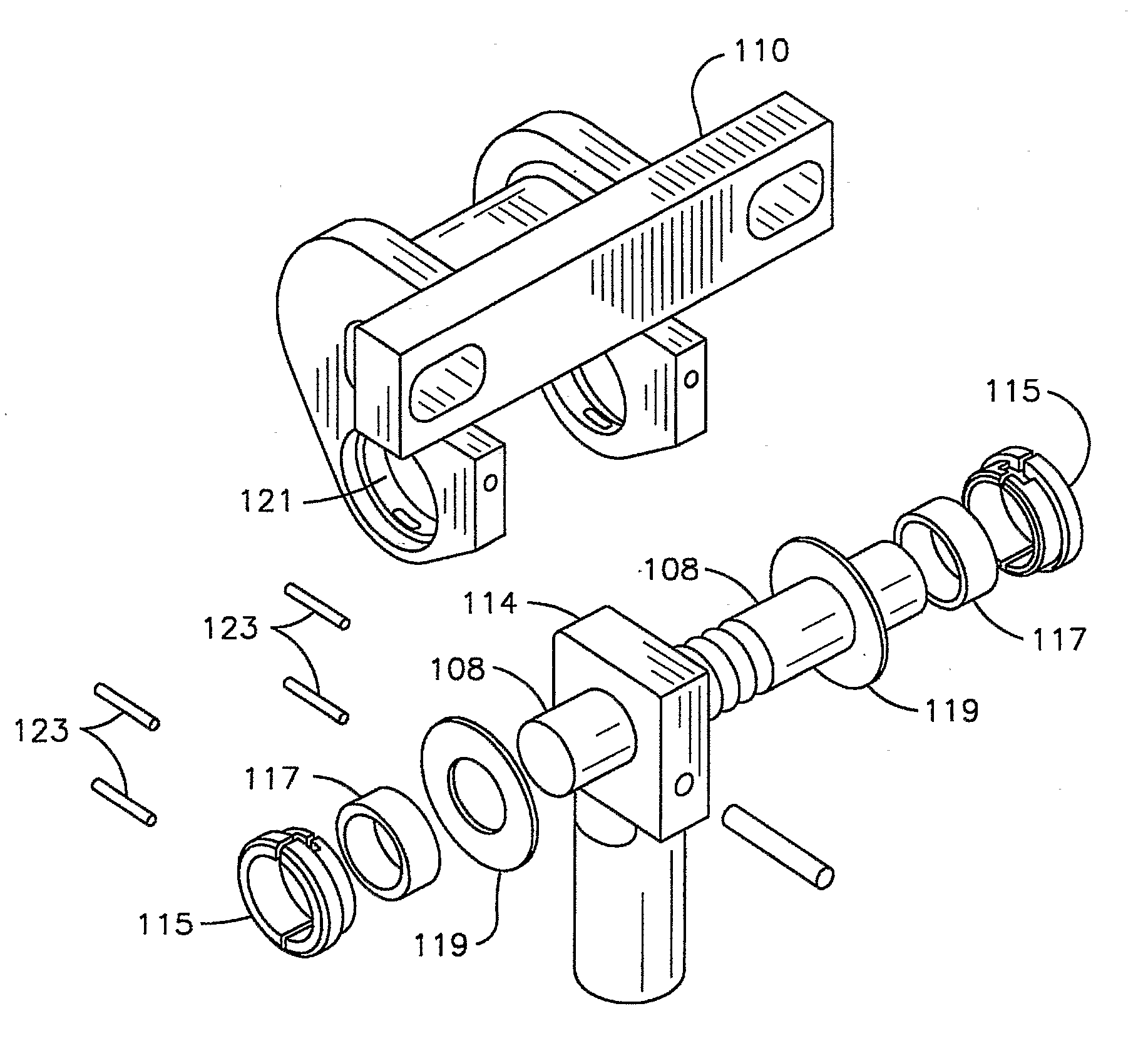
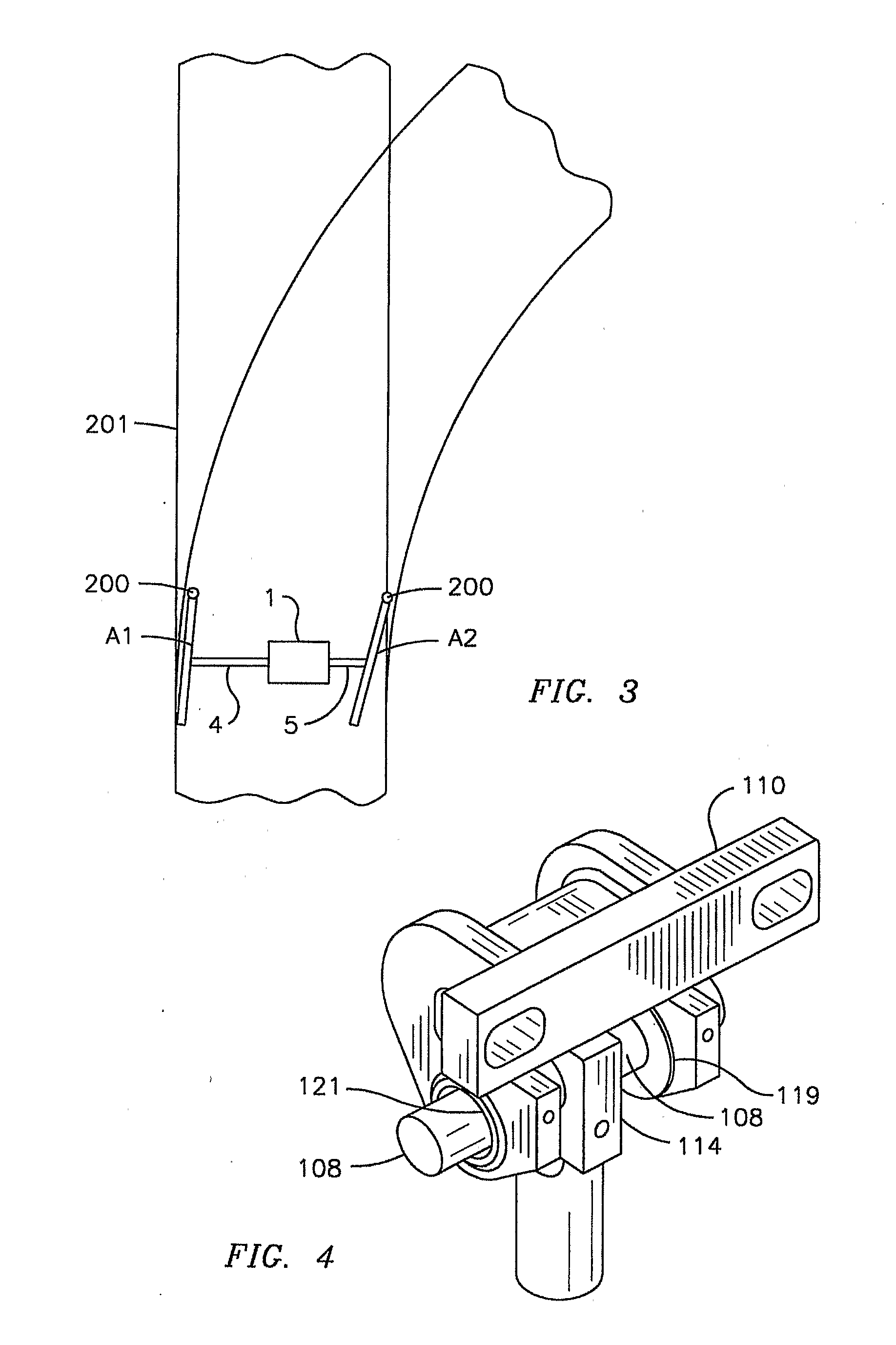
[0019]With reference to the figures, exemplary embodiments of the invention will now be described. Exemplary embodiments of the invention are disclosed below specific to a pivoting connector. The scope of the exemplary embodiment of the invention is not limited to a pivoting connector within a switch machine. Specifically, exemplary embodiments of the invention may be implemented in association with other moving parts of a switch machine.

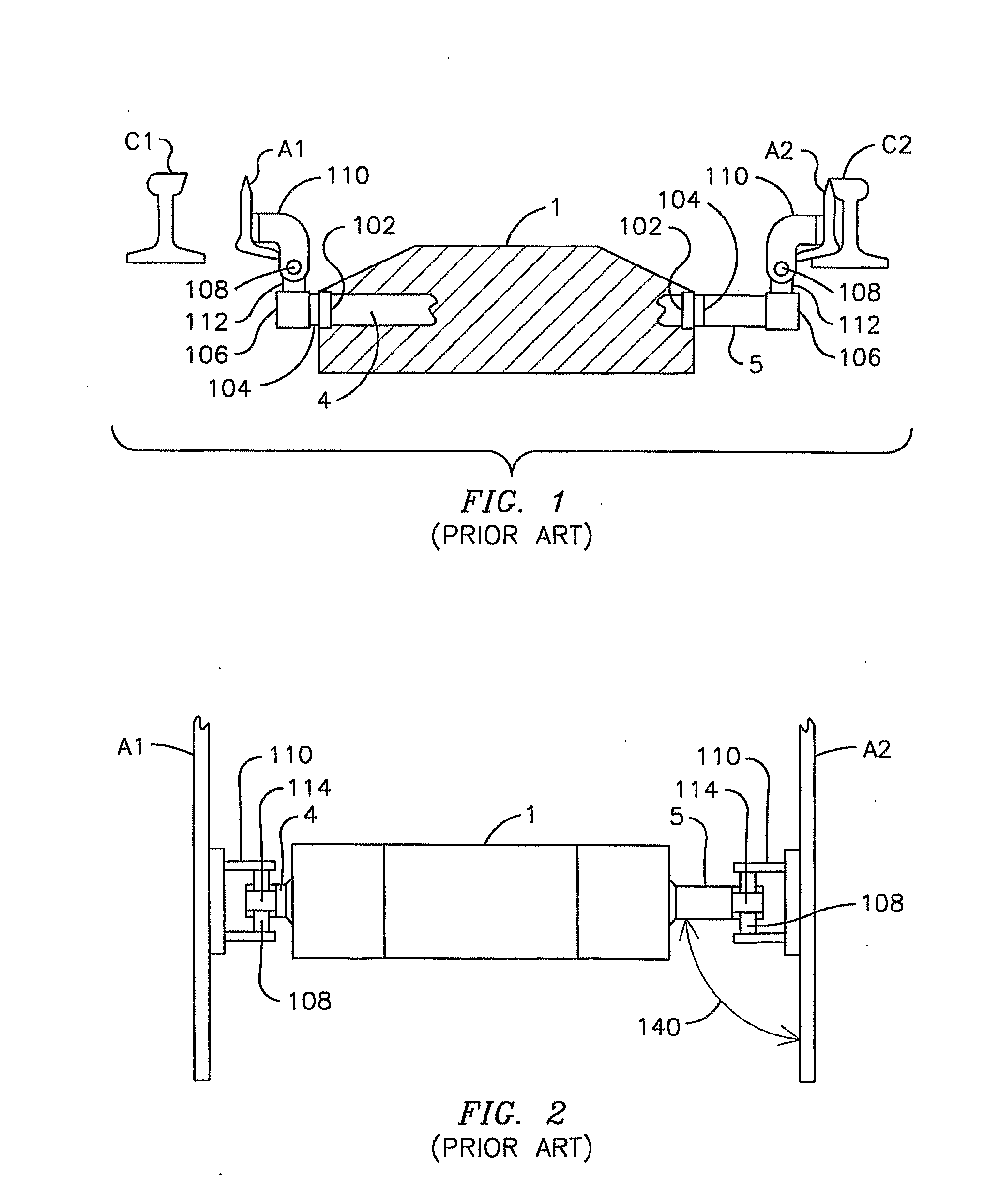
[0020]FIG. 1 illustrates a side elevation view of prior art connectors for a switch machine with the switch machine housing 1 itself being shown in section so as to show the location of a bearing 102 and a seal 104 on each operating rod 4, 5. The bearing 102 aligns the operating rod 4, 5 to move along a line of action on the axis of the internal mechanism of the switch machine, while the seal 104 seals out water and other contaminants which could cause deterioration or even malfunctioning of the switch machine. A socket 106 is provided at the outer ...


PUM


Abstract

In a railroad switch for use with intersecting railroad rails and having two switch points interconnected by a switch machine between two switch point assemblies and connected thereto by an operating rod at each end of the switch machine, a system for a greaseless switch point assembly having a mounting clip and a pivot pin for connecting each operating rod to its associated switch point, the greaseless switch point assembly having a bushing proximate a part of the pivot pin that fits within an opening in the mounting clip, and an insertion device extending into the opening proximate the bushing.

Description

[0001]This application claims priority of Provisional Patent Application Ser. No. 60 / 748,241, filed on Dec. 7, 2005, which is incorporated herein by reference.FIELD OF THE INVENTION[0002]Exemplary embodiments of the invention are in the field of railroad switching devices, namely, the equipment which is used to displace railroad switch points. More specifically, exemplary embodiments of the invention refer to a greaseless pivoting connector and / or clip.BACKGROUND OF THE INVENTION[0003]A railroad switch point consists of tapered rail sections that are capable of being selectively displaced between two different lateral positions at a rail switch and then locked in the selected position in order to facilitate the desired routing of a train passing through the switch. The two switch points are typically displaced by rods extending from an assembly that is referred to herein as a “switch machine”. Inside the switch machine the rods are usually connected to a motive mechanism which provi...

Claims


Application Information

Patent Timeline
Patent Type & Authority Applications(United States)
IPC IPC(8): B61L5/02
CPCB61L5/026
Inventor BIAGIOTTI, MAURIZIO
Owner GENERAL ELECTRIC CO
Learn More