Liquid container, liquid supplying system and circuit board for liquid container

Inactive Publication Date: 2009-02-26
CANON KK
View PDF20 Cites 18 Cited by
  • Summary
  • Abstract
  • Description
  • Claims
  • Application Information

AI Technical Summary

Benefits of technology

[0009]Accordingly, it is a principal object of the present invention to provide a liquid container, a liquid supplying system comprising the container, a manufacturing method for the container, a circuit board for the container and a liquid containing cartridge, wherein light emission control of displaying devices such as LED are carried out through non-contact communication using a common antenna for a plurality of carrying positions for the ink containers. According to another aspect of the present invention, there is provided a liquid container, a liquid supplying system comprising the container, a manufacturing method for the container, a circuit board for the container and a liquid containing cartridge, wherein the light emission control for the displaying devices are effected on the basis of determination of the carried positions of the ink containers.

Problems solved by technology

In the case of the non-PC printing, this is not possible.
If, for example, the ink container is mounted on a wrong position, there is a liability that small ink remaining amount is displayed for another ink container which contains a sufficient amount of the ink.
However, in such a case, it is required to manufacture ink containers which are different depending on the color and / or kind of the ink, with the result of disadvantages in terms of manufacturing efficiency and / or cost.
With such a structure, if the read color information does not meet the carrying position, the erroneous mounting of the ink container is discriminated.
However, this structure results in increased number of signal lines.
The increase of the number of the signal lines increases the cost particularly in such printers.
On the other hand, in order to reduce the number of wiring leads, it would be effective to employ a so-called common signal line using a bus connection, but simple use of such a common signal line as bus connection cannot determines the ink containers or the carrying positions of the ink containers.

Method used


Image

  • Liquid container, liquid supplying system and circuit board for liquid container
  • Liquid container, liquid supplying system and circuit board for liquid container
  • Liquid container, liquid supplying system and circuit board for liquid container

Examples


Embodiment Construction

[0069]The description will be made as to the embodiments of the present invention in conjunction with the accompanying drawings, in the following order:

1. Mechanical Structure:

1.1 Ink Container:

1.2 Modified Example:

1.3 Ink Container Mounting Portion:

1.4 Recording Device:

2. Control System:

2.1 General Arrangement:

2.2 Connecting Portion:

2.3 Control Process:

3. Other Embodiments:

1. Mechanical Structure:

1.1 Ink Container (FIG. 1-FIG. 5):

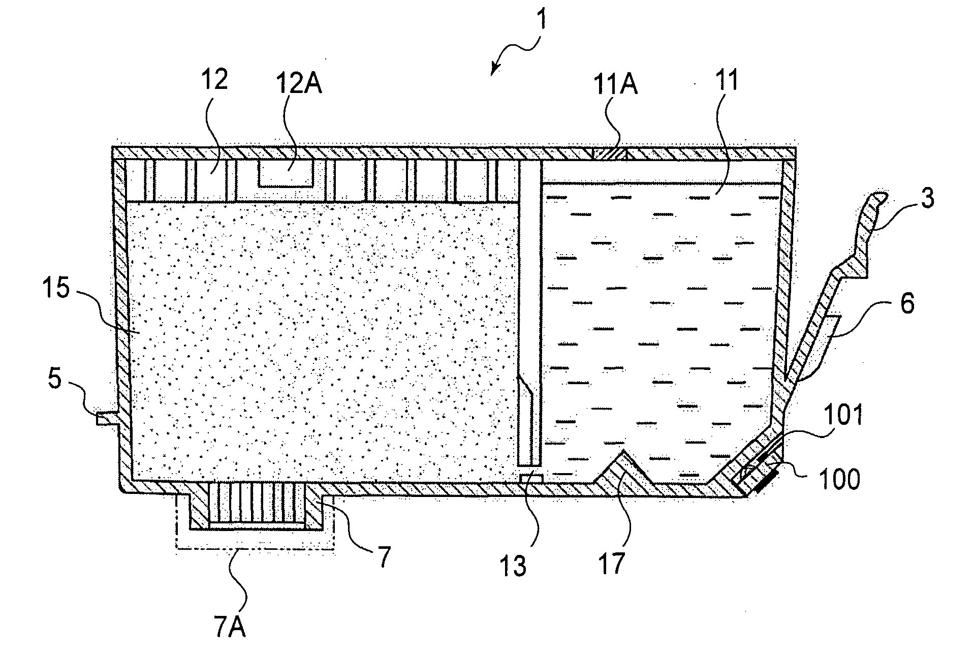
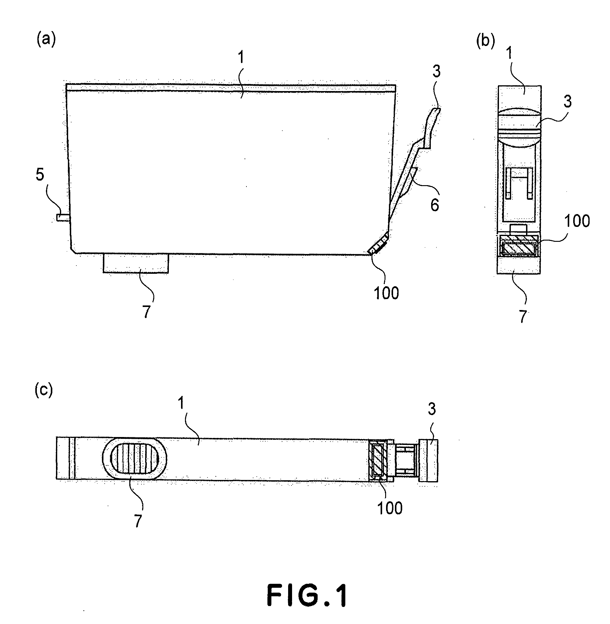
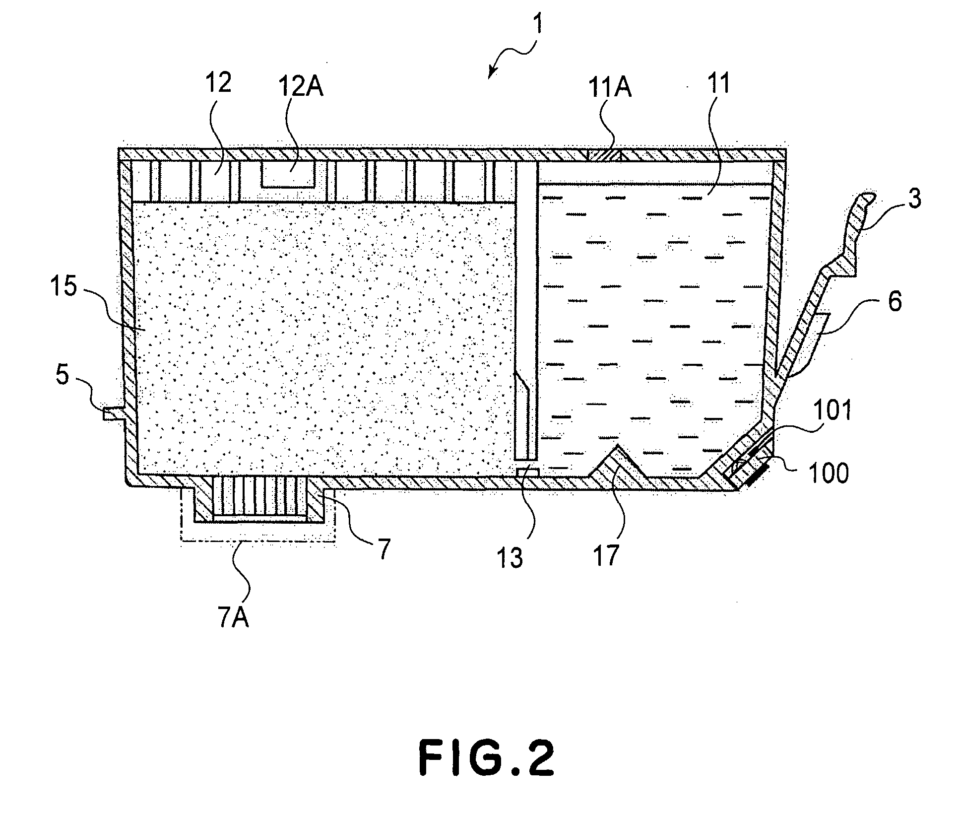
[0070]FIG. 1 is a side view (a), a front view (b) and a bottom view (c) of an ink container according to a first embodiment of the present invention. FIG. 2 is a sectional side elevation of the ink container according to the first embodiment of the present invention. In the following descriptions, the front side of the ink container is the side which is faced to the user who is manipulating the ink container (mounting and demounting operation of the ink container), which provides the user with information (by light emission of LED which will be described h...


PUM


Abstract

A liquid container detachably mountable to a recording apparatus to which a plurality of liquid containers are detachably mountable, wherein the recording apparatus includes an apparatus antenna and photoreceptor means, the liquid container includes a container antenna communicatable with the apparatus antenna without physical contact therebetween; an information storing portion capable of storing at least individual information of the liquid container; a light emitting portion; and a controller for controlling light emission of the light emitting portion in response to a correspondence between a signal indicative individual information supplied through the container antenna and the information stored in the information storing portion.

Description

TECHNICAL FIELD[0001]The present invention relates to a liquid container, a liquid supplying system comprising the container, a manufacturing method for the container, a circuit board for the container and a liquid containing cartridge. More particularly, the present invention relates to a liquid container which is usable with ink jet recording and which is capable of notifying a state of the liquid container such as a remaining ink amount of the ink container, by light emitting means such as a LED, to a liquid supplying system comprising the container, to a manufacturing method of the container, to a circuit board for the container, and to a liquid containing cartridge comprising the container.BACKGROUND ART[0002]With recent wider use of digital camera, the demand is increasing for printing with the digital camera being directly connected with a printer (recording device), that is, non-PC printing. Another increasing demand is for printing by setting a card type information memory ...

Claims


Application Information

Patent Timeline
IPC IPC(8): B41J2/175
CPCB41J2/17546B41J2002/17573B41J2/17566B41J2/175B41J2/17
Inventor WATANABE, KENJIROMATSUMOTO, HARUYUKI
Owner CANON KK
Why Eureka
Try Eureka