Electric brake device

a technology of brake device and electric brake, which is applied in the direction of electrodynamic brake system, mechanical apparatus, transportation and packaging, etc., can solve the problem that the electric brake device becomes unsusceptible, and achieve the effect of achieving the responsibility of braking performan

Inactive Publication Date: 2009-03-05
NIPPON SOKEN +1
View PDF13 Cites 18 Cited by
  • Summary
  • Abstract
  • Description
  • Claims
  • Application Information

AI Technical Summary

Benefits of technology

[0010]Accordingly, it is a primary object of the present invention to provide an improved electric brake device which excels in the responsibility of braking performance and which does not deteriorate in the responsibility despite the wear of braking members.

Problems solved by technology

Further, because such a wear compensating mechanism can be arranged at a position away from a friction member of the braking member, the electric brake device becomes unsusceptible to the influences of vibration and heat, and therefore, it can be realized to make the electric brake device hard to fail.

Method used


Image

  • Electric brake device
  • Electric brake device
  • Electric brake device

Examples


first embodiment

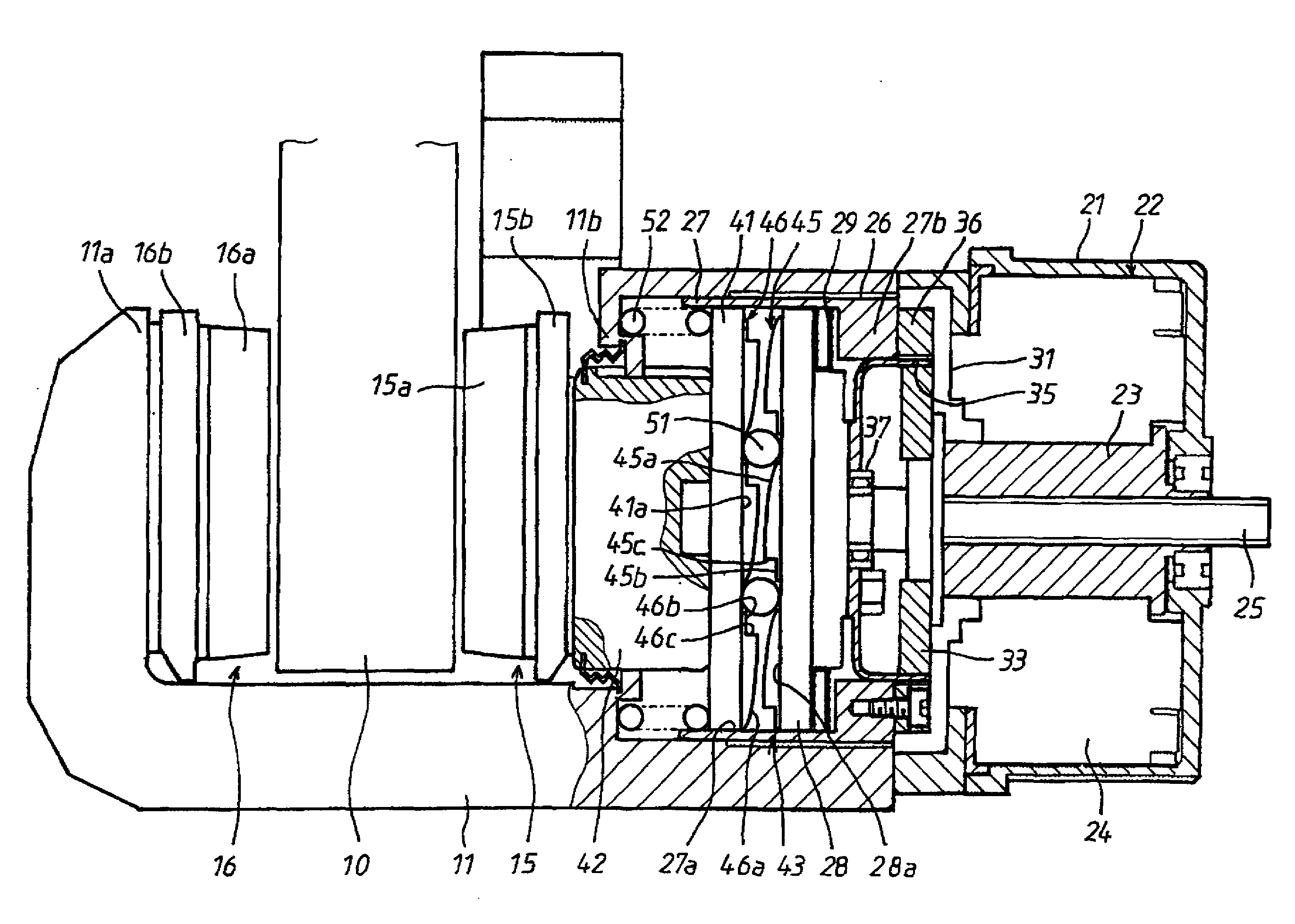
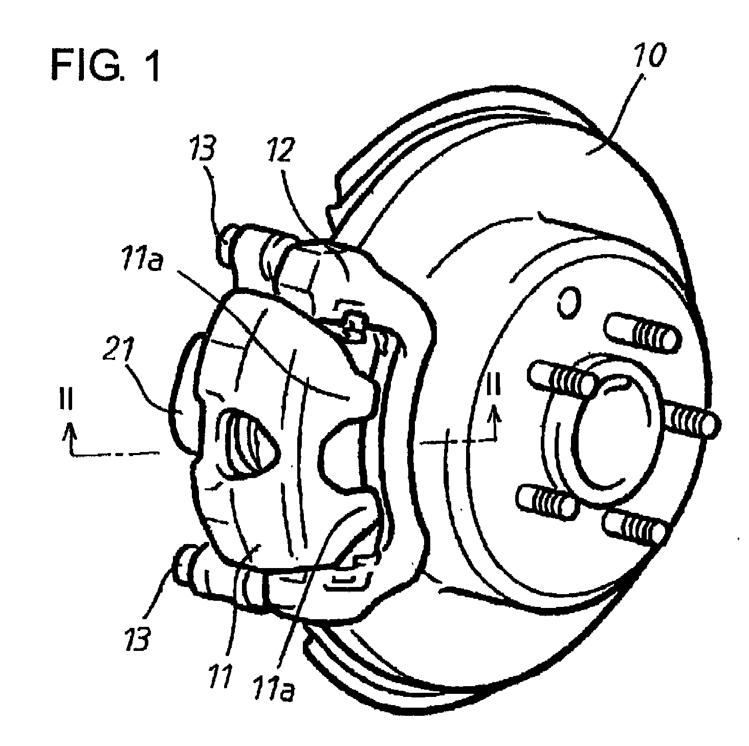
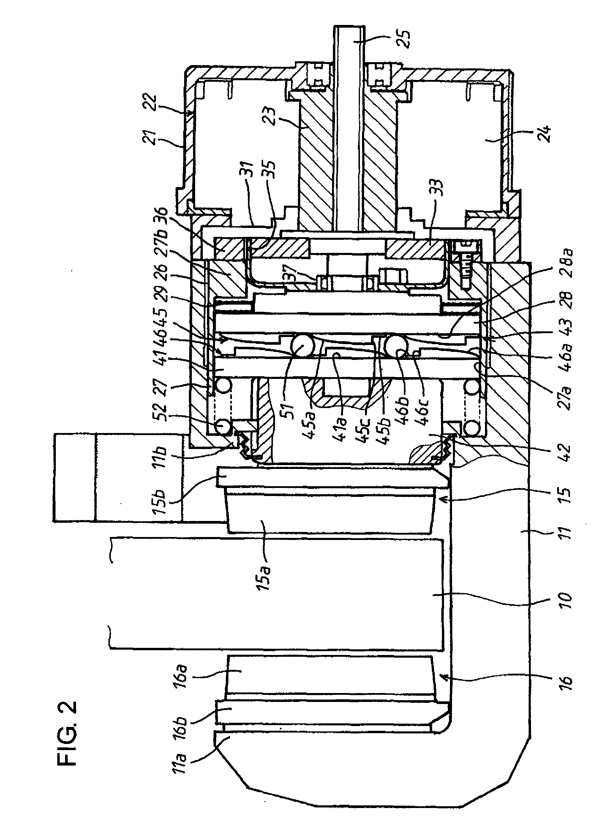
[0028]Hereafter, an electric brake device in a first embodiment according to the present invention will be described with reference to FIGS. 1 to 7. Referring now to FIGS. 1 and 2, numeral 10 denotes a brake rotor of the electric brake device, and the brake rotor 10 is bodily attached to a wheel of an automotive vehicle (both not shown) incorporating the electric brake device. At a part of the circumferential surface of the brake rotor 10, a caliper 11 taking a U-shape in cross-section is arranged to be astride the brake rotor 10. The caliper 11 is supported by a mount member 12 secured on a vehicle body side, through a pair of slide pins 13 and is movable by a short distance in the axial direction of the brake rotor 10.

[0029]A pair of first and second brake pads 15, 16 as braking members are arranged to face opposite sides of the brake rotor 10 in the axial direction. The first brake pad 15 arranged inside of the brake rotor 10, that is, on the vehicle body side is attached to a pr...

second embodiment

[0066]FIG. 8 shows a second embodiment according to the present invention. The difference from the first embodiment is that in the first embodiment, the friction resistance at the screw engagement between the screw hole 26 of the caliper 11 and the screw member (thrust force support member) 27 works to hold the screw member 27 in a stationary state, whereas in the second embodiment, there is separately provided an operation resistance application mechanism for positively applying operation resistance to the screw member 27, so that the screw member 27 can be reliably held in the stationary state. Therefore, hereinafter, description will be made mainly regarding the differences from the first embodiment, whereas description will be omitted regarding the components which are the same in construction and are given the same reference numerals as those in the first embodiment.

[0067]In FIG. 8, the screw member 27 is screwed into the screw hole 26 formed in the caliper 11. A screw compensa...

third embodiment

[0073]FIGS. 10 and 11 show a third embodiment according to the present invention. The difference from the foregoing second embodiment is that an operation resistance acting in radial directions is applied to the screw member 27.

[0074]Referring to FIGS. 10 and 11, storage pockets 71 (refer to FIG. 11) are formed in the flange portion 27b of the screw member 27 at, e.g., two places (preferably, two diametrically opposed places) in the circumferential direction. The storage pockets 71 open at the external surface of the flange portion 27b. Friction engaging pieces 72 of square shape are fitted respectively in the storage pockets 71 to be slidable in the radial directions only. Radial external surfaces of the friction engaging pieces 72 are formed as screw portions 72a which are screw-engaged with the screw hole 26 of the caliper 11. Springs 73 each comprising a coil spring as urging member are interposed between respective bottom portions of the storage pockets 71 and the friction enga...


PUM


Abstract

An electric brake device comprises a caliper holding braking members and having an electric motor attached thereto, a reduction mechanism for transmitting an input rotation of one input element thereof from the electric motor to two output elements thereof at reduced speeds, a rotation-linear motion converting mechanism for converting the rotation of one of the output elements into a linear motion of one of the braking members, and a thrust force support member connected to the other output element and screw-engaged with the caliper, wherein the rotation-linear motion converting mechanism is supported by the thrust force support member to be movable together in a thrust direction and is provided with rotation limiting portions for limiting the rotation in a reverse direction of the one output element to a predetermined range, and wherein the thrust force support member is set to be greater in resistance to operation than the rotation-linear motion converting mechanism.

Description

[0001]This application is based on and claims priority under 35 U.S.C. 119 with respect to Japanese Applications No. 2007-224902 filed on Aug. 30, 2007 and No. 2008-179620 filed on Jul. 9, 2008, the entire contents of which are incorporated herein by reference.BACKGROUND OF THE INVENTION[0002]1. Field of the Invention[0003]The present invention relates to an electric brake device of the type that rotational motion from an electric motor is reduced by a reduction gear and is converted by a rotation-linear motion converting mechanism into a linear motion to press braking members against a brake rotor.[0004]2. Discussion of the Related Art[0005]As vehicle brake devices, as described in Japanese unexamined, published patent application No. 2002-213505, there has been known an electric brake device wherein rotational motion from an electric motor is converted by a ball-screw mechanism into a linear motion to press braking members against a brake rotor.[0006]In the vehicle brake devices o...

Claims


Application Information

Patent Timeline
Patent Type & Authority Applications(United States)
IPC IPC(8): F16D55/02
CPCF16D65/14F16D2065/386F16D2127/007F16D2125/36F16D2121/24
Inventor TSURUTA, TOMOHIKOTOMINAGA, MOTONORIARAKAWA, HARUOTAKESHITA, TAKAYUKIYAMADA, JINYOKOYAMA, TAKAHISA
Owner NIPPON SOKEN
Why Eureka
Try Eureka