Terminal Connection Structure

a technology of connection structure and terminal, which is applied in the direction of coupling device connection, coupling device details, securing/insulating coupling contact members, etc., can solve the problem of difficult terminal inserting under the ribs, and achieve the effect of easy and reliable connection

Active Publication Date: 2009-03-12
YAZAKI CORP
View PDF6 Cites 34 Cited by
  • Summary
  • Abstract
  • Description
  • Claims
  • Application Information

AI Technical Summary

Benefits of technology

[0008]In the light of the aforementioned circumstances, an object of the present invention is to provide a terminal connection structure in which the terminal with wire is not detached from a stud bolt even if upward force is applied to the wire after the stud bolt is inserted from above into a bolt insertion hole of the terminal, thus allowing the nut to be reliably and easily attached to the stud bolt and in which the terminal can be easily fit on the stud bolt.
[0016]At the insertion, the belt portions of the terminals pass the ribs to be positioned below the ribs. In this case, the ribs prevent the terminals from being detached upward. It is therefore possible to screw and fasten the nuts to the stud bolts onto the terminals prevented from being detached without holding the wires extending from the terminals in particular. Accordingly, the terminals can be easily and reliably connected to the stud bolts.

Problems solved by technology

In the case of the fixing method of standing the stud bolt in the terminal connection portion and fitting the terminal onto the stud bolt, the pair of ribs provided at the same height to prevent detachment of the terminal make it difficult to insert the terminal under the ribs.

Method used


Image

  • Terminal Connection Structure
  • Terminal Connection Structure
  • Terminal Connection Structure

Examples


Embodiment Construction

[0026]Hereinafter, a description is given of an embodiment of the present invention with reference to the drawings.

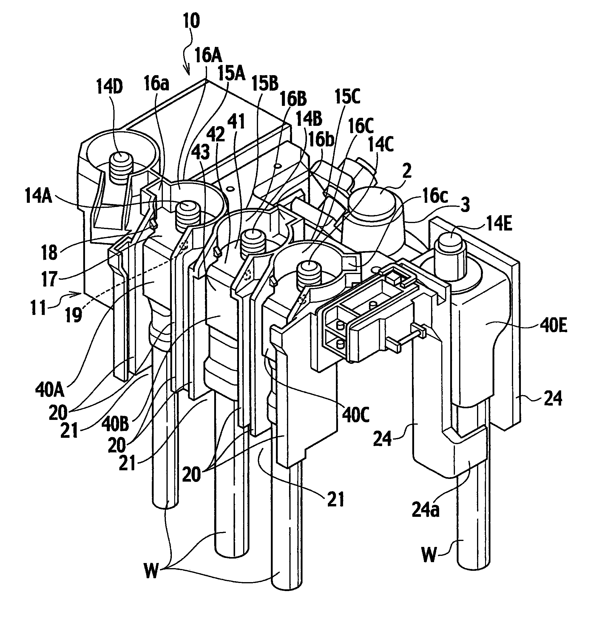
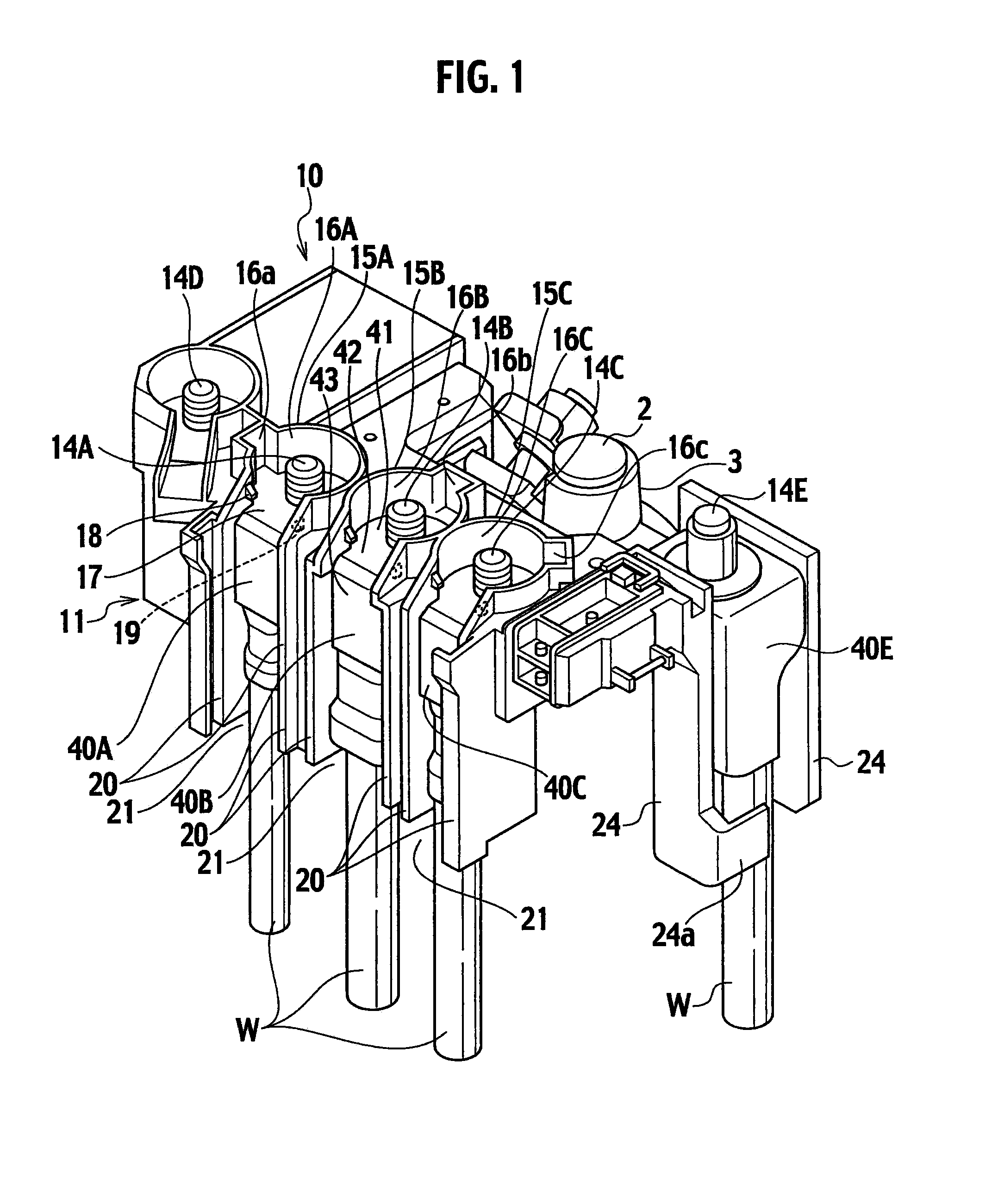
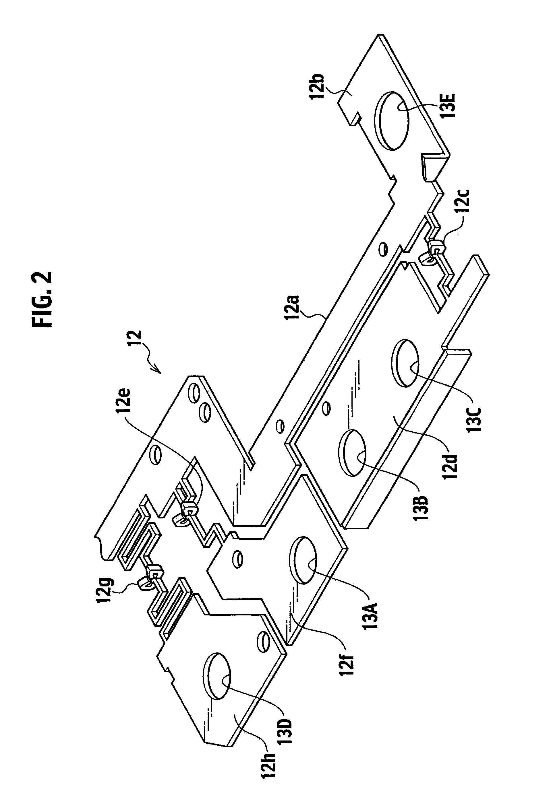
[0027]A terminal connection structure of the embodiment includes a fusible link unit 10 directly mounted on a battery 1 as shown in FIGS. 1 and 9. The fusible link unit 10 is attached to a battery post 2 with a battery terminal 3 interposed therebetween. The fusible link unit 10 includes a busbar 12 press-molded as shown in FIG. 2 within a housing 11 made of mold resin.

[0028]The busbar 12 includes: an input plate portion 12a having an input terminal plate 12b at an end; and output plate portions 12d, 12f, and 12h connected to the input plate portion 12a through fuse elements (fusible portions) 12c, 12e, and 12g, respectively. In the input terminal plate 12b, a hole 13E, through which a stud bolt 14E is inserted, is formed. In the output plate portions 12d, 12f, and 12h, holes 13A to 13D, through which the stud bolts 14A to 14D are inserted, are formed, respectively.

[002...


PUM


Abstract

In a terminal connection structure, a stud bolt is stood and inserted into a hole of a top plate portion of a terminal, and the nut is screwed and fastened to the stud bolt on the top plate, thus connecting the terminal to the stud bolt. A terminal accommodation section is formed by a tubular wall around the stud bolt. It has an opening and ribs at a part of a circumference thereof, and allows the terminal fixed to the stud bolt from above. The opening is formed so as to fit on a belt portion extending from the top plate portion toward a fixing portion of the terminal. The ribs are protruded on the protection wall. The ribs prevent the terminal from being detached upward when the terminal is being temporarily lifted. The ribs are arranged at different heights in a top-bottom direction of the stud bolt.

Description

CROSS REFERENCE TO RELATED APPLICATION[0001]This application is based upon and claims the benefit of priority from Japanese Patent Application No. 2007-236727 filed on Sep. 12, 2007, the entire contents of which are incorporated herein by reference.BACKGROUND OF THE INVENTION[0002]1. Field of the Invention[0003]The present invention relates to a terminal connection structure for connecting a stud bolt standing on a fusible link unit or the like to a terminal with wire (called as an LA terminal) using a nut.[0004]2. Description of the Related Art[0005]To fix a perforated terminal with wire (generally called as an LA terminal) to a terminal connection portion of the other member using a bolt, before the bolt is fastened, the terminal is positioned so as not to move. In this case, the bolt is inserted into a hole of the terminal with the terminal engaged with a rib (a latch craw) which restricts the position of the terminal to the terminal connection portion of the other member, and th...

Claims


Application Information

Patent Timeline
Patent Type & Authority Applications(United States)
IPC IPC(8): H01R13/68H01R13/40H01R4/34H01R9/24
CPCH01R11/12H01R13/42H01R11/28H01H2085/0555H01H85/12H01H2085/025
Inventor OHASHI, NORIHIROTAKAHASHI, ASAKO
Owner YAZAKI CORP
Why Eureka
Try Eureka