Disposable syringe device auxiliary unit for preventing iatrogenic infection through needle

a syringe and auxiliary unit technology, applied in the direction of packaging foodstuffs, pharmaceutical containers, packaged goods, etc., can solve the problems of accidental needle stick, cap is detached, exposed needle stuck under or in the skin,

Inactive Publication Date: 2005-02-01
ABE KOICHIRO
View PDF8 Cites 1 Cited by
  • Summary
  • Abstract
  • Description
  • Claims
  • Application Information

AI Technical Summary

Benefits of technology

An object of the present invention is to provide a disposable syringe device auxiliary unit for preven

Problems solved by technology

Therefore, when chemicals are injected into or blood is collected from a patient using the disposable syringe device, the cap is detached, and the exposed needle is stuck under or in the skin, in the muscle or in the blood pipe of the patient.
One of the most serious problems in medical disasters, which happen to doctors, nurses, and medical practicians in a medical site, is a so-called accidental needle stick in which a used needle is stuck in a hand or a finger of them.
In addition to the above, however, there is also a possibility that the accidental needle stick happens when a cap is attached to the needle again.
Further, in an ope

Method used


Image

  • Disposable syringe device auxiliary unit for preventing iatrogenic infection through needle
  • Disposable syringe device auxiliary unit for preventing iatrogenic infection through needle
  • Disposable syringe device auxiliary unit for preventing iatrogenic infection through needle

Examples


first embodiment

the present invention will be described below with reference to FIGS. 1 to 6.

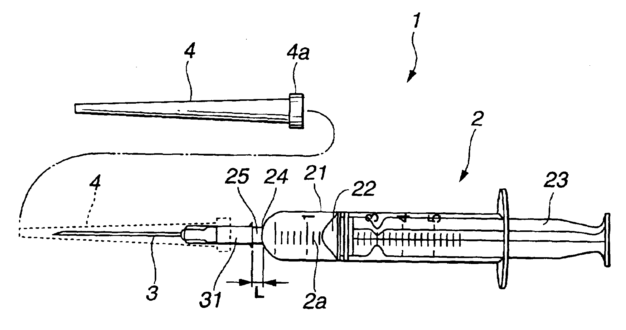
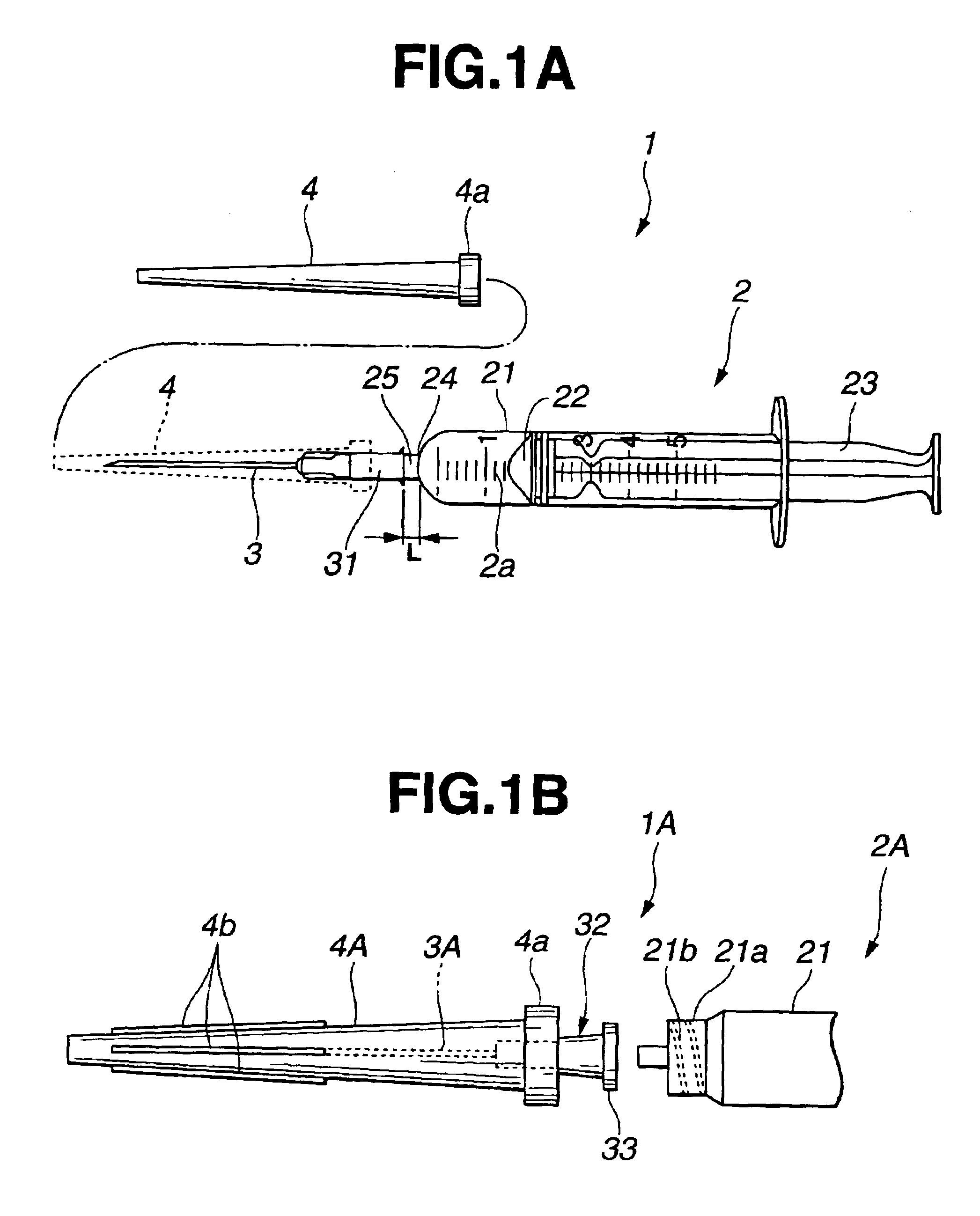
A disposable type syringe device (hereinafter, referred to simply as a “disposable syringe device”) will be described below with reference to FIG. 1A.

As shown in the figure, a disposable syringe device 1 is composed of a disposable syringe 2 acting as a syringe barrel, a needle 3 detachably attached to the disposable syringe 2, and a cylindrical cap 4 for preventing the needle 3 from being left in an exposed state.

The cap 4 covers the needle 3 as shown by a dotted line. With this arrangement, the needle 3 is prevented from being left in the exposed state. The disposable syringe 2, the needle 3, and the cap 4 have been sterilized.

The disposable syringe 2 is composed of an outer barrel 21 and an inner barrel 23 that is slidable with respect to the inner hole of the outer barrel 21. A scale 2a is formed on the outer surface of the outer barrel 21 to measure an amount of chemicals, and the like. A stopper 22 is...

second embodiment

the present invention will be described below with reference to FIGS. 8 to 11.

In the second embodiment, a needle separation auxiliary unit 81, which is composed of a separation / guide groove 52 acting as a needle separating section and a slanting surface 55, is arranged as a type of syringe auxiliary units as shown in FIG. 8, in place of the syringe auxiliary unit 5A of the first embodiment in which the cap holding section is integrated with the needle separating section. Further, a cap holding auxiliary unit 82 acting as a type of the syringe auxiliary units is arranged such that it is provided with a plurality of cap clamping / holding sections 83a acting as a cap holding unit as shown in FIG. 9A.

Then, as shown in FIG. 10, a syringe barrel / needle hold / separation unit is arranged by mounting the needle separation auxiliary unit 81 and the cap holding auxiliary unit 82 on first and second auxiliary unit mounting sections 61 and 65 of the needle accommodation box 6, respectively.

As show...


PUM

PropertyMeasurementUnit
Thicknessaaaaaaaaaa
Angleaaaaaaaaaa
Lengthaaaaaaaaaa

Abstract

A disposable syringe device auxiliary unit of the present invention for preventing iatrogenic infection through a needle includes a cap holding section for disposing and holding therein a cap which covers, when a medical treatment is performed, a needle positioned at the extreme end of a syringe barrel constituting a disposable syringe device; and a needle separating section for separating the needle, which is covered with the cap and fitted on an end of the syringe barrel, therefrom.

Description

This application claims benefit of Japanese Application No. 2001-189973 filed on Jun. 22, 2001, the contents of which are incorporated by this reference.BACKGROUND OF THE INVENTION1. Field of the InventionThe present invention relates to a disposable syringe device auxiliary unit for enabling a cap to be attached to a needle or enabling the needle to be removed from a disposable syringe device with one hand.2. Description of the Related ArtRecently, disposable syringe devices that are discarded when they are used once, that is, so-called disposable syringe devices are widely used to prevent iatrogenic infection through syringe devices. The disposable syringe device is composed of a sterilized disposable syringe and a sterilized needle mounted thereon. The needle is covered with a sterilized cap.Therefore, when chemicals are injected into or blood is collected from a patient using the disposable syringe device, the cap is detached, and the exposed needle is stuck under or in the skin...

Claims


Application Information

Patent Timeline
IPC IPC(8): A61M5/32A61G12/00
CPCA61M5/3205A61M5/3213A61M5/3204Y10T29/49822A61M2005/3215Y10T29/53687
Inventor ABE, KOICHIRO
Owner ABE KOICHIRO
Why Eureka
Try Eureka