Dishwasher with targeted sensing and washing

a technology of targeted sensing and automatic dishwasher, which is applied in the direction of cleaning using liquids, tableware washing/rinsing machines, house cleaners, etc., can solve the problems of limiting the selection of wash cycles, less than optimal cleaning and resource usage, and using wash cycles

Inactive Publication Date: 2009-03-19
WHIRLPOOL CORP
View PDF11 Cites 61 Cited by
  • Summary
  • Abstract
  • Description
  • Claims
  • Application Information

AI Technical Summary

Benefits of technology

[0009]A method of washing utensils in an automatic dishwasher having a wash chamber in which the utensils are received comprises determining the presence of utensils in at least one sub-portion of the wash chamber, and spraying liquid onto the utensils in the at least one sub-portion to effect the washing of the utensils.

Problems solved by technology

Such dishwashers also typically provide a limited selection of wash cycles.
This can result in wash liquid being sprayed in areas that have no utensils if the dishwasher contains less than a full load of utensils.
Cleaning and resource usage is less than optimal due to the spraying of wash liquid in empty areas that could better be concentrated in areas occupied by utensils.
The availability of only a limited number of cycles can result in using wash cycles that may be inappropriate for some loads or for mixed loads.
For example, a “pots and pans” cycle may be suitable for heavily-soiled cooking utensils, but may be overly hot and long for tableware, thereby contributing to excessive water, detergent, and energy consumption.
Furthermore, selection of a wash cycle based upon the majority of the utensils in the dishwasher may result in incomplete cleaning of more heavily soiled utensils.

Method used


Image

  • Dishwasher with targeted sensing and washing
  • Dishwasher with targeted sensing and washing
  • Dishwasher with targeted sensing and washing

Examples


first embodiment

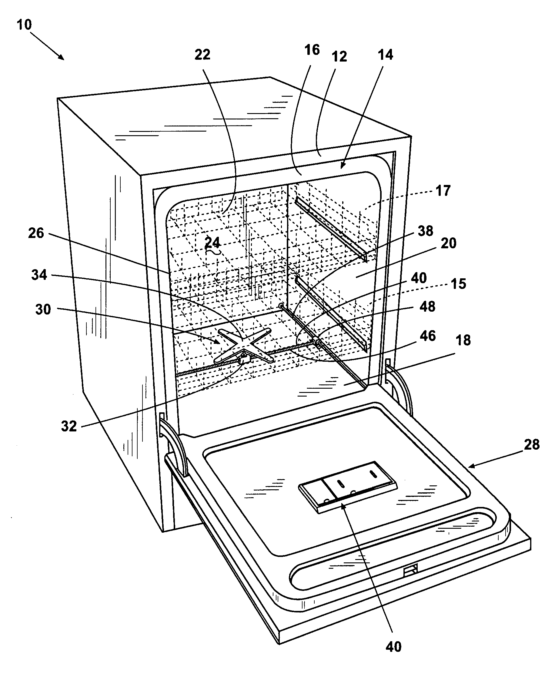
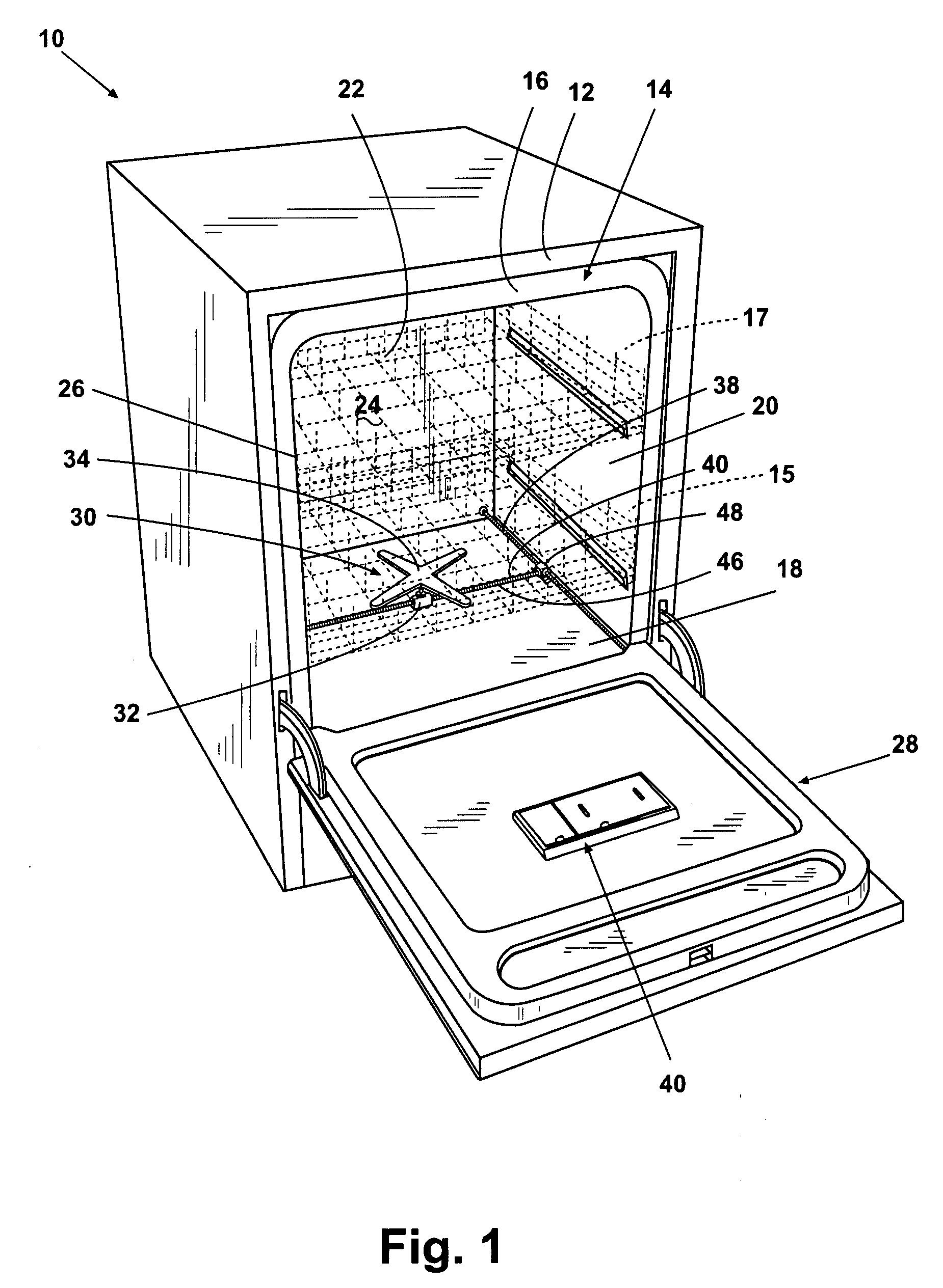
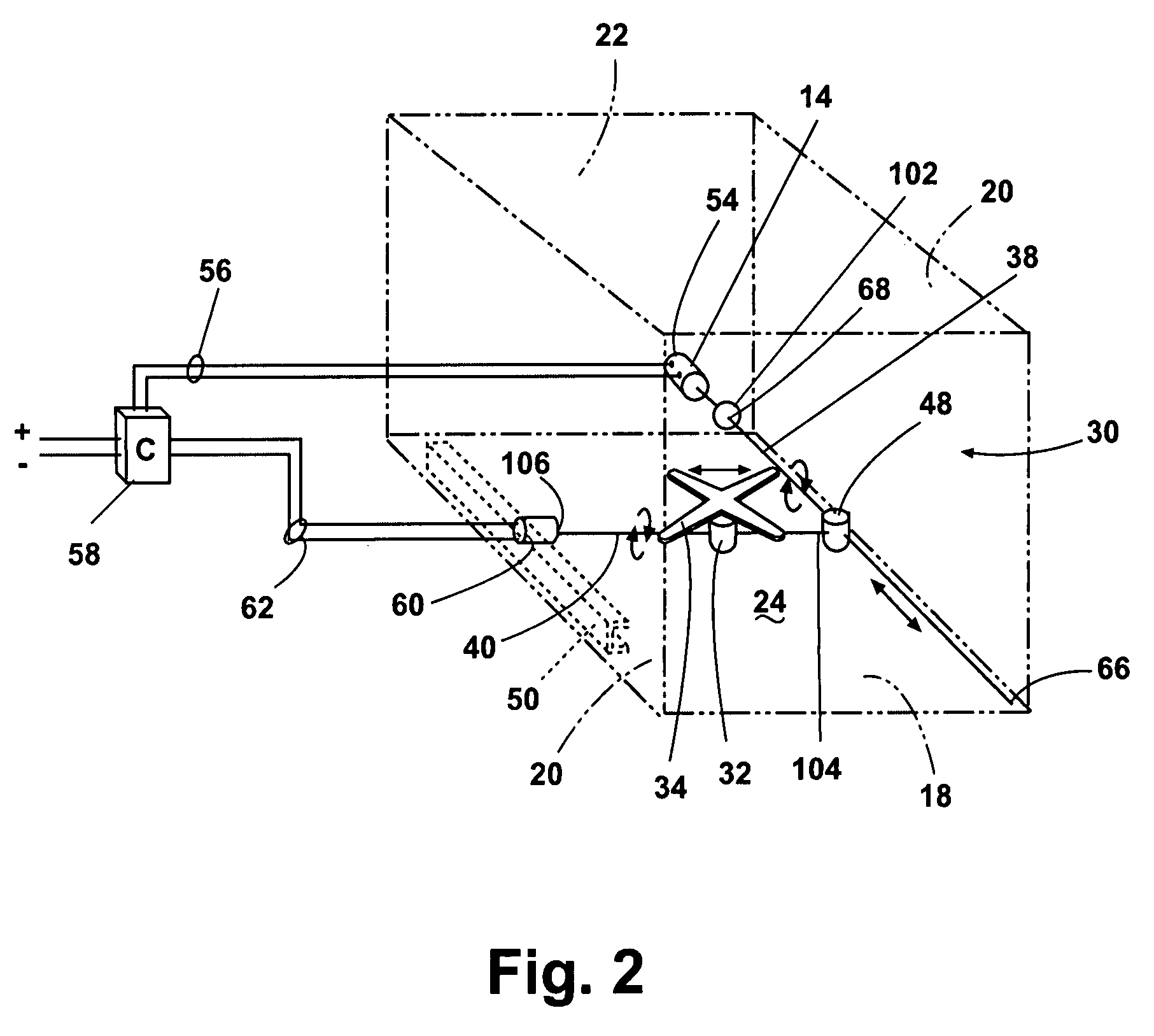
[0025]FIG. 2 illustrates the sprayer assembly 30 comprising a drive and control system. The fixed lead screw 38 is an elongated rod-like member having helical threads extending along the full length thereof, and having a first end 66 and a second end 68. The fixed lead screw 38 is supported at the first end 66 for rotation about its longitudinal axis by a suitable bearing assembly (not shown) located at the front of the wash chamber 24. The second end 68 of the fixed lead screw 38 can extend through a fixed lead screw aperture 102 in the rear wall 22 for direct coupling with a suitable electric motor 54 located outside the wash chamber 24 for controlled rotation of the fixed lead screw 38 about its longitudinal axis. Preferably, the fixed lead screw aperture 102 is suitably configured for watertightness by the employment of well-known devices, such as seals, boots, grommets, and the like, enabling the operable coupling of the motor 54 to the fixed lead screw 38.

[0026]The movable lea...

second embodiment

[0053]FIGS. 6-8 illustrate the positionable sprayer assembly. In this embodiment, the movable sprayer assembly 120 is supported in a support frame 122 configured to fit within the wash chamber 24 as an integrated unit. The support frame 122 comprises a pair of spaced side rails 124 extending along the side walls 20 and connected by a pair of spaced end rails 126 to form a generally rectilinear frame 122. One of the side rails 124 is provided with an inwardly-directed flange 118 extending the length of the side wall 124. The sprayer 130 is similar to the sprayer 30 previously described herein, and is configured for delivering a rotating spray of wash liquid to utensils in the wash chamber 24. A transverse shaft 132 extends from side-to-side between the side rails 124, and is threaded generally as previously described. The transverse shaft 132 is operably coupled to a transmission 134, which in turn is coupled through a square drive shaft 138 to a first drive gear 142. The first drive...


PUM


Abstract

An automatic dishwasher comprises a housing defining a wash chamber for holding utensils to be washed, a movable sprayer fluidly coupled with a source of liquid and having at least one directionally-controllable outlet for controllably spraying liquid into the wash chamber, and a controller operably coupled to the movable sprayer to control the direction of the directionally-controllable outlet to spray liquid in at least one preselected location within the wash chamber.

Description

BACKGROUND OF THE INVENTION[0001]1. Field of the Invention[0002]The invention relates to spray assemblies and soil load sensing devices for automatic dishwashers.[0003]2. Description of the Related Art[0004]Conventional household automatic dishwashers frequently have rotating spray arms for spraying cleaning and rinsing liquids on utensils. Such dishwashers also typically provide a limited selection of wash cycles. For example, a prior art dishwasher can provide a default wash cycle appropriate for most utensil loads and soil levels. Other cycles may include a “pots and pans” cycle for cleaning cooking utensils which may be heavily soiled. A “fragile” cycle can be used for china, crystal, glassware, and the like.[0005]Prior art dishwashers also typically comprise a fixed spray arm assembly in the center of the dishwasher floor that sprays wash liquid uniformly throughout the wash chamber. This can result in wash liquid being sprayed in areas that have no utensils if the dishwasher c...

Claims


Application Information

Patent Timeline
Patent Type & Authority Applications(United States)
IPC IPC(8): A47L15/18A47L15/46
CPCA47L15/18A47L15/22A47L2501/04A47L2401/04A47L15/4295
Inventor SUNDARAM, SATHISH ANDREASHARKEY, JOSEPH KARLWELIN, LUIS FERNANDOBERTSCH, ROGER JAMESWILSON, DONALD J.
Owner WHIRLPOOL CORP
Why Eureka
Try Eureka