Bimodal kite system

a kite system and bimodal technology, applied in the field of bimodal kite systems, can solve problems such as net power generation

Inactive Publication Date: 2009-03-19
GOOGLE VENTURES 2012 LP +1
View PDF15 Cites 56 Cited by
  • Summary
  • Abstract
  • Description
  • Claims
  • Application Information

AI Technical Summary

Problems solved by technology

However, one problem in this method of generating power is that net power is generated only in the event that more power

Method used


Image

  • Bimodal kite system
  • Bimodal kite system
  • Bimodal kite system

Examples


Embodiment Construction

[0013]The invention can be implemented in numerous ways, including as a process, an apparatus, a system, a composition of matter, a computer readable medium such as a computer readable storage medium or a computer network wherein program instructions are sent over optical or communication links. In this specification, these implementations, or any other form that the invention may take, may be referred to as techniques. A component such as a processor or a memory described as being configured to perform a task includes both a general component that is temporarily configured to perform the task at a given time or a specific component that is manufactured to perform the task. In general, the order of the steps of disclosed processes may be altered within the scope of the invention.

[0014]A detailed description of one or more embodiments of the invention is provided below along with accompanying figures that illustrate the principles of the invention. The invention is described in conne...


PUM


Abstract

A kite is disclosed. The kite comprises a first control element coupled to the kite in a first tether-force configuration, wherein the first control element is used to maintain controlled flight of the kite in the first tether-force configuration during a power generating phase. The kite further comprises a second control element coupled to the kite in a second tether-force configuration, wherein the second control element is used to maintain controlled flight of the kite in the second tether-force configuration during a recovery phase, and wherein during the recovery phase a tether force associated with the second tether-force configuration is reduced as compared to the tether force associated with the first tether-force configuration during the power generating phase

Description

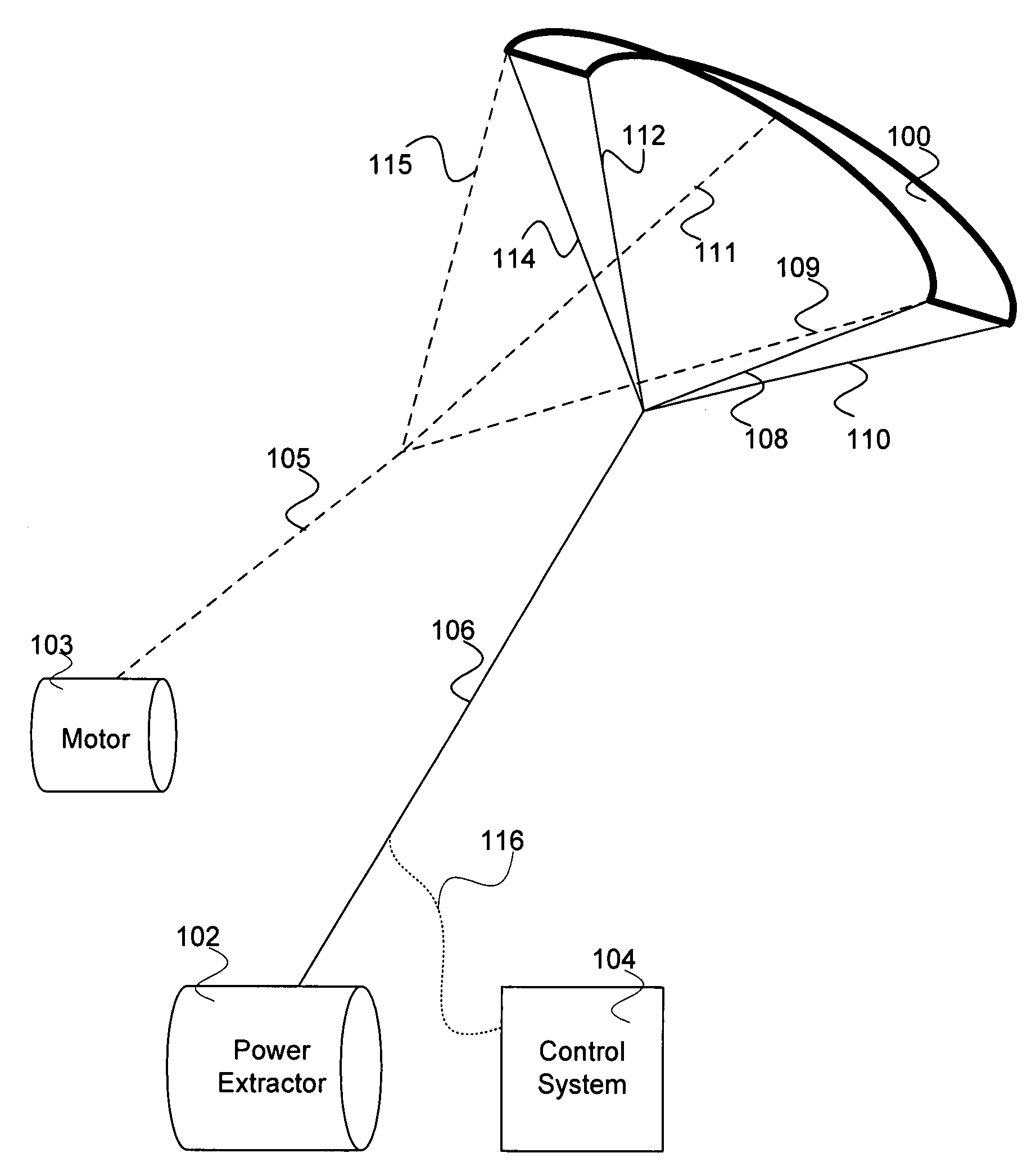
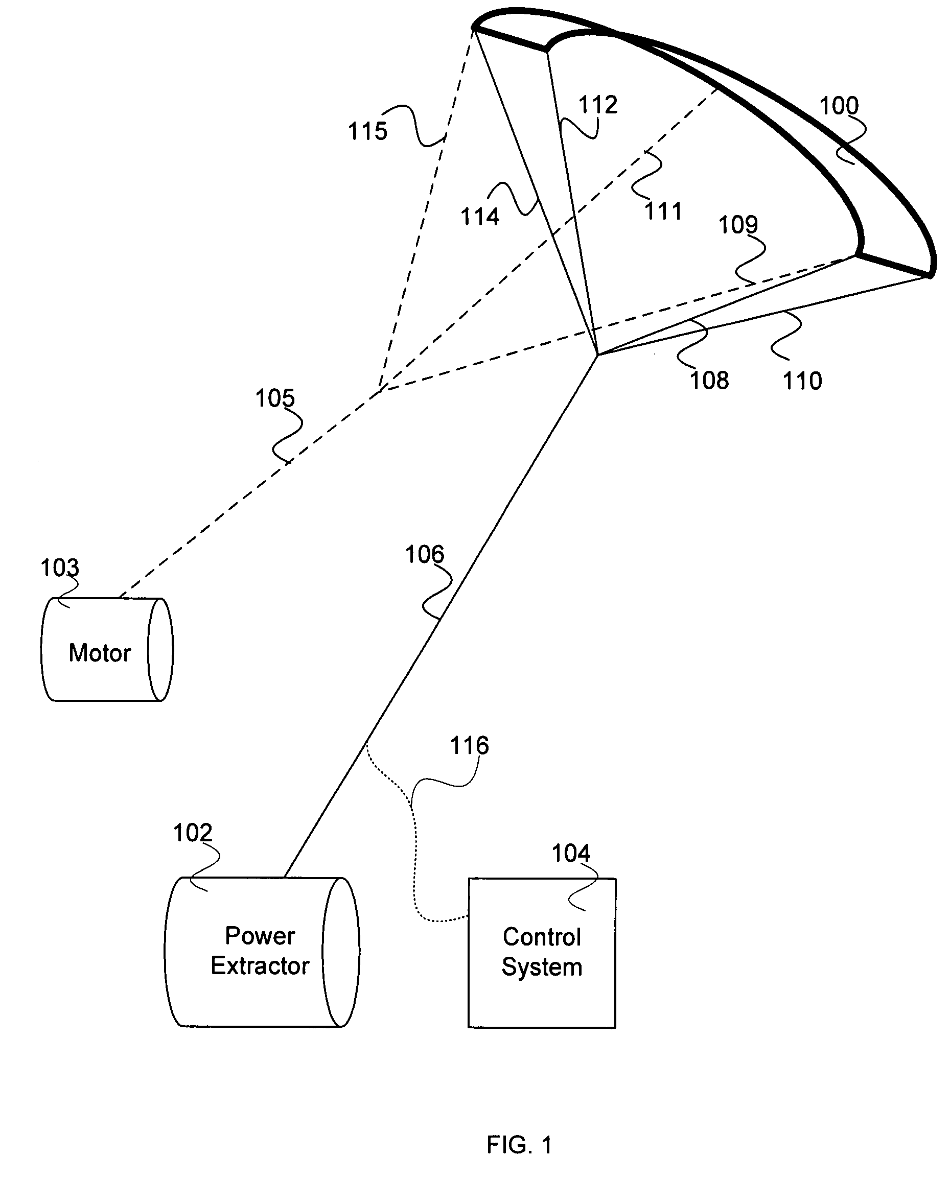
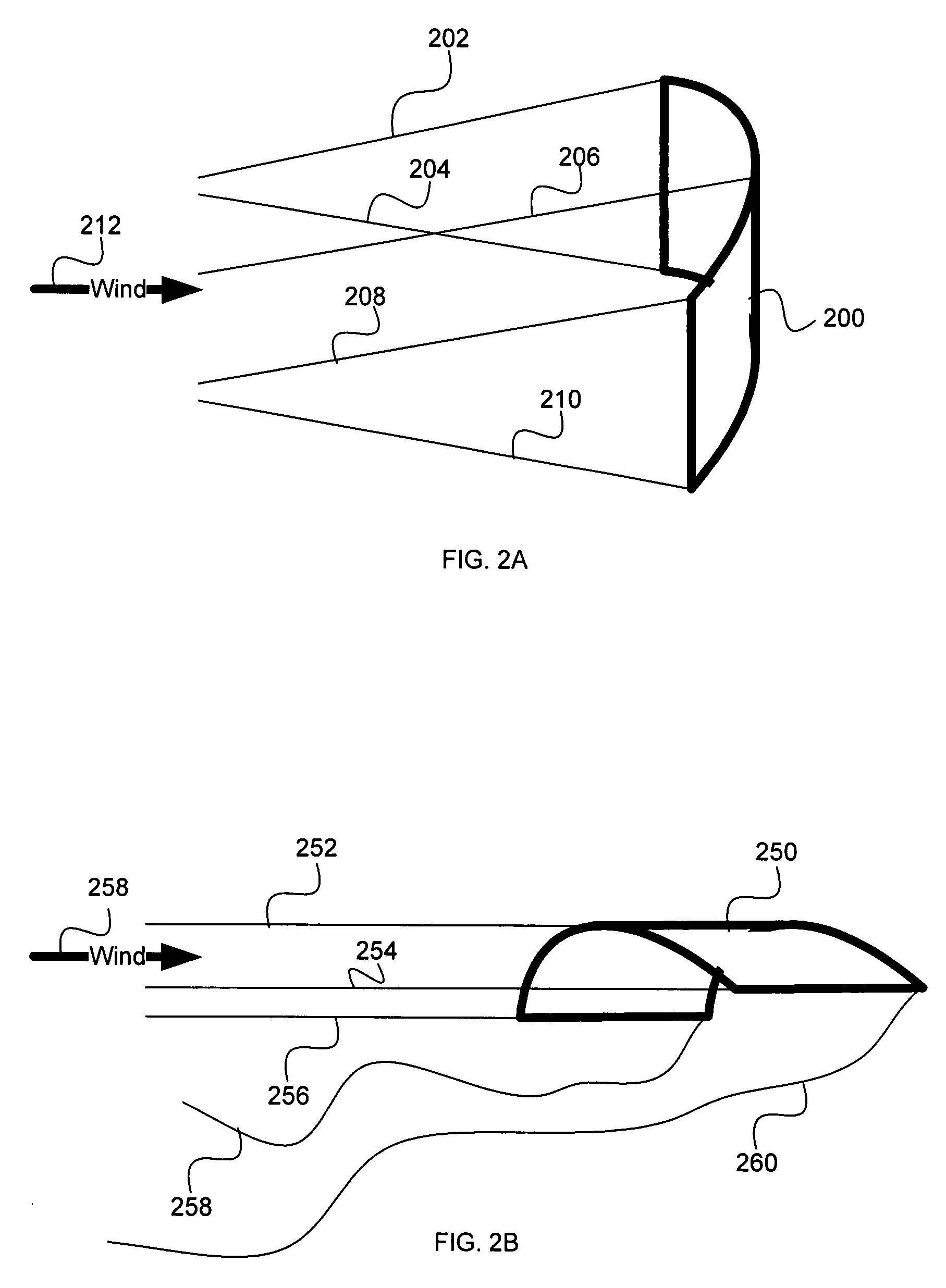
BACKGROUND OF THE INVENTION[0001]A kite can be used to generate power from the wind. Power can be generated when a kite tether line is pulled out by the wind on the kite. The kite tether line is then pulled in. The process can then be repeated. However, one problem in this method of generating power is that net power is generated only in the event that more power is generated as the kite is let out in the power generating phase, than is used to pull in the kite in the recovery phase. Also, in reducing the power required to pull in the kite, the kite must still be flown in a controllable manner so that it can be maintained appropriately aloft. It would be beneficial to be able to generate power using a kite without loss of control of the kite.BRIEF DESCRIPTION OF THE DRAWINGS[0002]Various embodiments of the invention are disclosed in the following detailed description and the accompanying drawings.[0003]FIG. 1 is a block diagram illustrating an embodiment of a bimodal kite system.[00...

Claims


Application Information

Patent Timeline
IPC IPC(8): B64C31/06
CPCB64C31/06Y02E10/70F03D5/00
Inventor GRIFFITH, SAULLYNN, PETERMONTAGUE, DONHARDHAM, CORWIN
Owner GOOGLE VENTURES 2012 LP
Why Eureka
Try Eureka