Universal stop for a slidable window

a technology of sliding window and universal stop, which is applied in the direction of door/window fittings, mechanical devices, wing accessories, etc., can solve the problems of slamming window stop breaking, too much force being delivered from sliding window, and limited force that tumbler can absorb

Inactive Publication Date: 2009-04-16
NEWELL OPERATING COMPANY
View PDF4 Cites 7 Cited by
  • Summary
  • Abstract
  • Description
  • Claims
  • Application Information

AI Technical Summary

Problems solved by technology

While this window stop has been very effective in this application, the amount of force that the tumbler can absorb is limited.
In some applications, too much force can be delivered from the sliding window.
The high impact of the sliding window against the stop causes the tumbler to overrotate, sometimes breaking the window stop.
By operating the latch, the bolt extends directly out of the housing into the path of a sliding window sash, thus limiting movement of the sash.
Because the window stop housing has separate cavities to accommodate the latch and bolt, however, the stop is not as compact in size.
In addition, the second window stop is more costly than the window stop having the rotating tumbler.
This results in an essentially hollow sash window frame.
This causes window stop manufacturers to produce multiple housings based on anticipated frame member or wall thicknesses.
This increases attendant costs.
This also causes window manufacturers and assemblers to stock and inventory multiple window stops depending upon anticipated frame member thicknesses, increasing attendant costs for the window manufacturer.

Method used


Image

  • Universal stop for a slidable window
  • Universal stop for a slidable window
  • Universal stop for a slidable window

Examples


Embodiment Construction

[0035]While this invention is susceptible of embodiments in many different forms, there is shown in the drawings and will herein be described in detail, a preferred embodiment of the invention with the understanding that the present disclosure is to be considered as an exemplification of the principles of the invention and is not intended to limit the broad aspects of the invention to the embodiment illustrated.

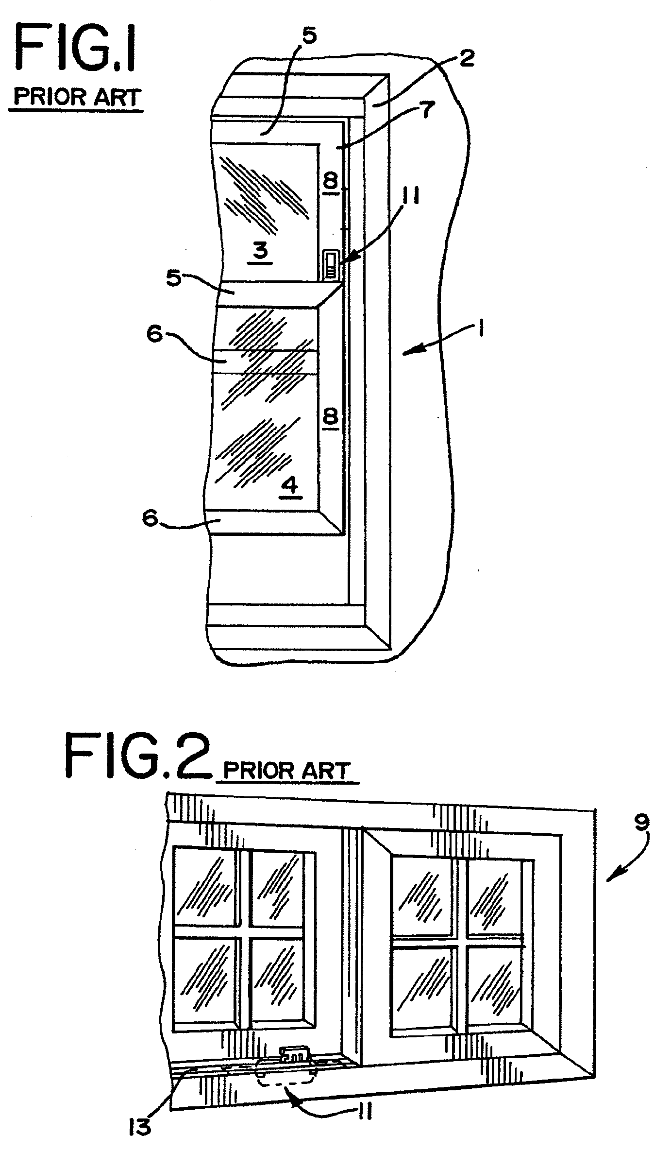
[0036]Referring to the drawings, FIG. 1 shows a prior art window stop 11 being used in a sash window assembly 1. The window assembly 1 includes a master frame 2 having an upper sash window 3 and a lower sash window 4 slidably mounted therein. Each sash window 3, 4 has a top rail 5, bottom rail 6 and a pair of vertical stiles 7. Each stile 7 is typically hollow and includes a front wall or frame member 8. The prior art window stop 11 is shown installed in the vertical stile 7 of the upper sash window 3, being mounted to the front wall 8 thereof.

[0037]FIG. 2. shows a horizontal...


PUM


Abstract

A window stop is provided. The window stop includes a housing defining a cavity and having mount structure. The mount structure is adapted to be mounted to a wall having a thickness between a range of thicknesses from a minimum to a maximum thickness. A bolt is mounted within the cavity and moveable between a retracted position wherein the bolt is substantially located within the housing and a locking position wherein the bolt extends from within the cavity. Also provided is means for releasably holding the bolt in the retracted position and biasing means between the housing and the bolt for biasing the bolt towards the extended position.

Description

CROSS-REFERENCE TO RELATED APPLICATION[0001]The present application is a continuation of copending U.S. patent application Ser. No. 10 / 752,406, filed on Jan. 6, 2004, which application is incorporated by reference herein and made part hereof.TECHNICAL FIELD[0002]This invention relates generally to a device for selectively limiting the movement of a sliding member and more particularly concerns a window stop for selectively limiting the movement of a window that slides either horizontally or vertically along a track, the stop capable of being mounted in window frames or sash windows having frame members of varying thicknesses.BACKGROUND OF THE INVENTION[0003]Sliding window assemblies often include a pair of window sashes. One assembly is commonly referred to as a double-hung sash window. A double-hung window typically includes a window frame and a pair of window sashes mounted for vertical sliding movement, one relative to the other, within the window frame. Another window assembly m...

Claims


Application Information

Patent Timeline
Patent Type & Authority Applications(United States)
IPC IPC(8): E05C19/00E05C17/48E05C17/60
CPCE05C17/60E05C17/48Y10T292/62Y10T292/1031Y10T292/08
Inventor LUTFALLAH, ANTHONY G.
Owner NEWELL OPERATING COMPANY
Why Eureka
Try Eureka