Electrical connector

a technology of electrical connectors and connectors, applied in the direction of coupling contact members, coupling device connections, electrical apparatus, etc., can solve the problems of not being able to achieve the effect of using existing cable connectors, unable to be universally adopted and used, and no single, etc., to achieve the effect of quick and easy insertion into the receiving hole, quick and easy threaded mounting, and convenient insertion

Inactive Publication Date: 2009-04-30
BRIDGEPORT FITTINGS
View PDF3 Cites 17 Cited by
  • Summary
  • Abstract
  • Description
  • Claims
  • Application Information

AI Technical Summary

Benefits of technology

[0022]In addition, the first threaded end of the cable connector of the present invention incorporates a radially extending flange formed on the outer surface thereof directly adjacent the first threaded zone. In addition, the diameter of the first threaded zone is constructed for being associated with a conventional locking ring for being threadedly mounted therewith and inserted into receiving holes formed in conventional outlet boxes and/or junction boxes. In this way, the locking ring is advanced along the first threaded zone into locking abutting relationship with the wall of the outlet box or junction box and the radially extending flange. As a result, the first end of the cable connector of the present invention is quickly and easily inserted into receiving holes formed in conventional outlet boxes or junction boxes and quickly and easily securely mounted therein.
[0023]Furthermore, in the preferred embodiment of the present invention, the cable connector also incorporates a sealing bushing or grommet in addition to the inner sleeve member and housing member. By employing the sealing bushing or grommet, a rain tight and/or moisture tight cable connection is attained, enabling the cable connector of this embodiment to be used in a wide variety of applications where high levels of moisture may exist.
[0024]In order to assure that the desired rain tight and/or moisture tight cable connection is realized, the cable connector of the present invention is constructed for receiving the sealing bushing/grommet in the second end thereof, with the second end also being constructed for cooperative threaded mounted engagement with a gland nut or hex nut. In this construction, the sealing bushing/grommet is mounted in the cylindrical housing of the cable connector, with the gland nut or hex nut peripherally surrounding and ...

Problems solved by technology

However, in spite of the substantial effort that has been expended in developing such connectors, these prior art systems all have drawbacks or difficulties which prevent their universal adoption and use.
However, no single, easily installed, affective, construction exists for enabling the direct connection of a metal sheath cable with a junction box and/or outlet box which requires mounted engagement about a curved are...

Method used


Image

  • Electrical connector
  • Electrical connector
  • Electrical connector

Examples


Embodiment Construction

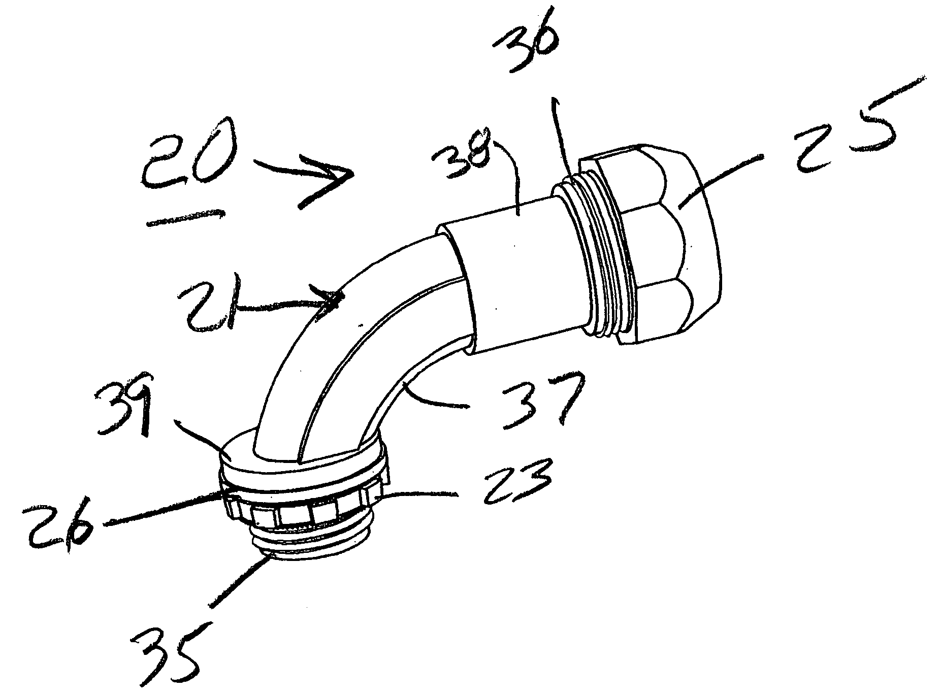
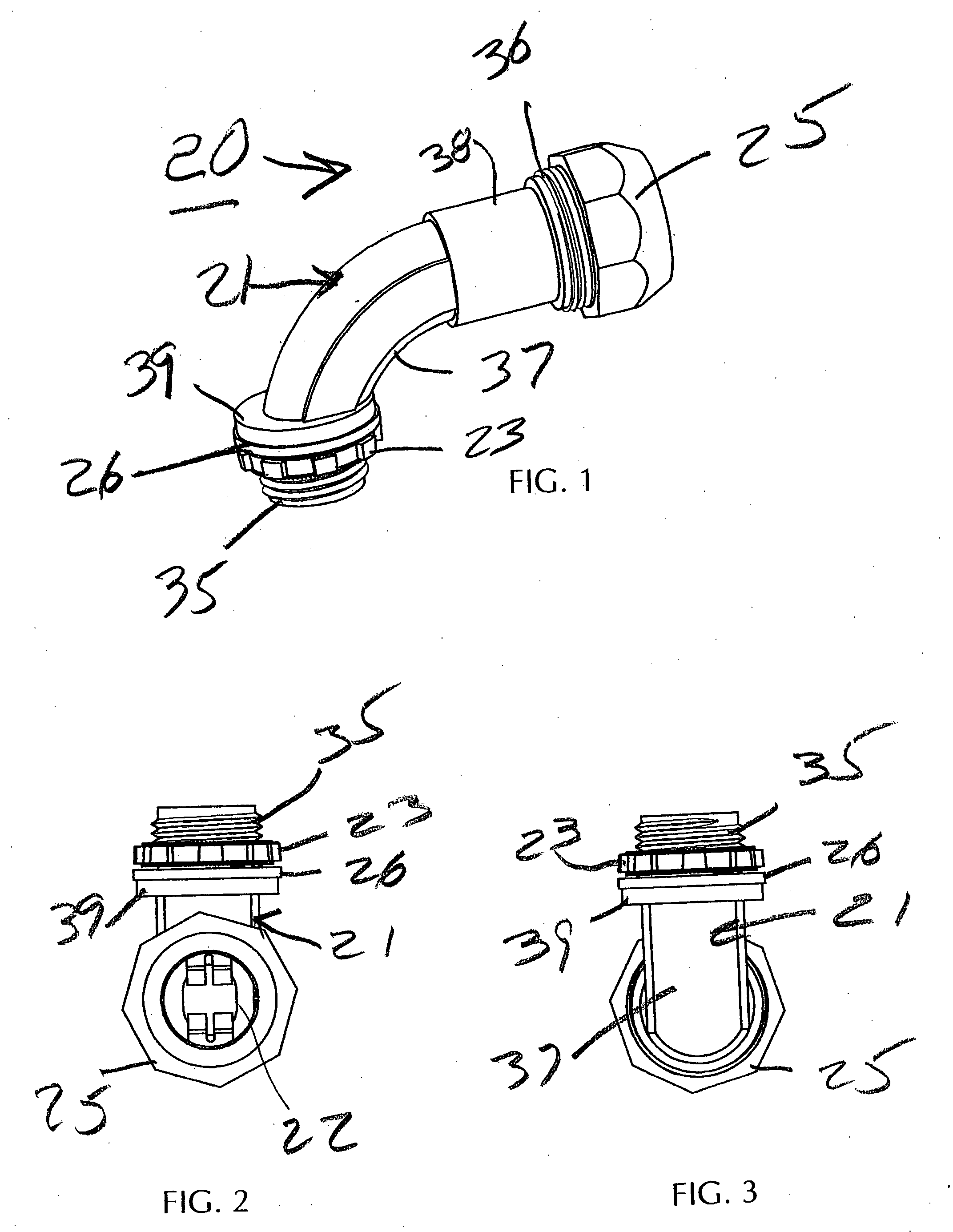
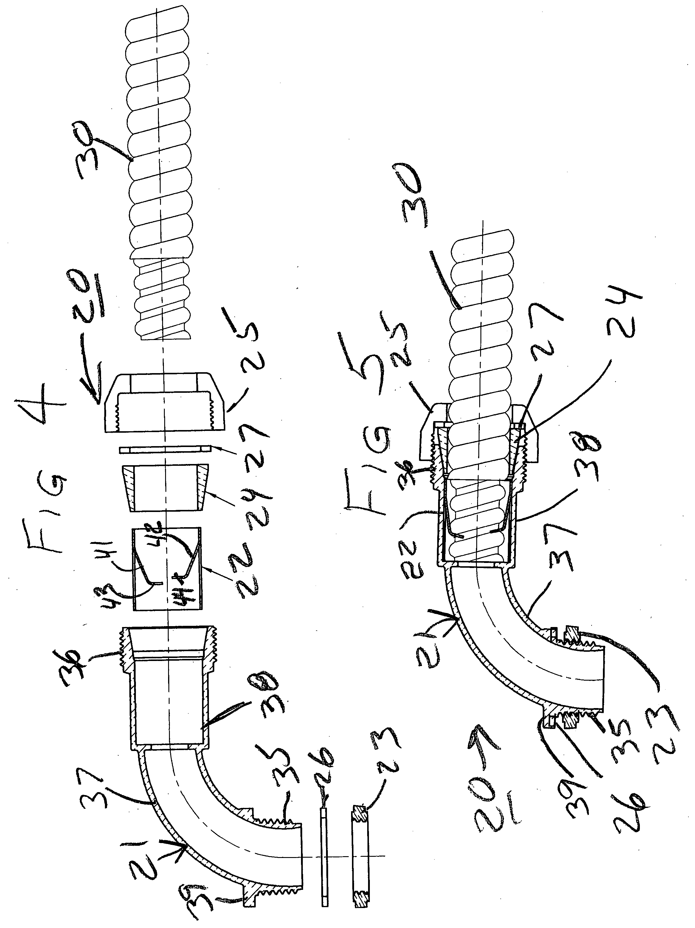
[0036]By referring to FIGS. 1-5, along with the following detailed disclosure, the construction and operation of this embodiment of electrical cable connector 20 of the present invention can best be understood. As will be evident to one having ordinary skill in the start, alternate constructions may be implemented using the teaching of the present invention without departing from the scope of this invention. However, it is to be understood that the constructions detailed herein are provided for exemplary purposes only, and are not intended as a limitation of the present invention.

[0037]As shown in FIGS. 1-5, the principal components which form cable connector 20 of the present invention comprise housing 21, inner sleeve member 22, locking ring 23, sealing bushing or grommet 24, and gland nut or hex nut 25. In addition, in the preferred embodiment, cable connector 20 also incorporates sealing rings 26 and 27. By forming these component in the manner detailed below, and assembling the...


PUM


Abstract

By providing two integrated components, an outer housing and an inner sleeve member, with the outer housing comprising a generally hollow cylindrical construction incorporating two threaded zones formed at both terminating ends, with the central portion of the hollow cylinder being formed in an arcuate curved shape, an efficient, easily manufactured and assembled cable connector is realized. Using the cable connector of the present invention, the desired metal sheath cable is quickly and easily secured to the connector and mounted in place in virtually any desired angular relationship, with complete assurance that the unwanted movement or withdrawal of the cable from the connector is virtually eliminated.

Description

TECHNICAL FIELD[0001]This invention relates to electrical connectors, and more particularly, to electrical connectors constructed for securing metal sheath cables to junction boxes and / or outlet boxes.BACKGROUND ART[0002]In the field of wiring homes and buildings, whether for new construction or for improvements or expansion, substantial development and product improvements have been made. Typically, these improvements are directed to enabling installers to securely mount any desired wiring in any desired location in the most efficient and quickest manner.[0003]In any particular installation or location, various cables must be interconnected to each other as well as connected to the primary power supply in a suitable power distributing junction box or fuse box. In each of these instances, metal sheath cables, within which the electric power carrying wires are contained, must be securely mounted to the housing of the junction box or outlet box, or connected to appropriate devices, in...

Claims


Application Information

Patent Timeline
IPC IPC(8): H01R13/02
CPCH01R31/06H01R9/0521
Inventor KIELY, KENNETH M.
Owner BRIDGEPORT FITTINGS
Why Eureka
Try Eureka