Electrical connectors

Active Publication Date: 2006-04-04
BRIDGEPORT FITTINGS LLC
View PDF8 Cites 16 Cited by
  • Summary
  • Abstract
  • Description
  • Claims
  • Application Information

AI Technical Summary

Benefits of technology

[0018]In accordance with the present invention, the conduit/cable connector is constructed with a cover member which is pivotally mounted to the base member and is constructed for being secured to the base member using a single screw. As a result, the operator is able to quickly and easily insert the flexible metal conduit and/or armored or metal clad cable into the receiving zone of the connector and then secure the cover member in clamping engagement with the flexible metal conduit and/or armored or metal clad cable by employing a single fastening screw. In this way, the desired secure mounted engagement and affixation of any desired flexible metal conduit and/or arm

Problems solved by technology

However, in spite of the substantial effort that has been expended in developing such connectors, these prior art systems have drawbacks or difficulties which prevent their universal adoption and use.
Although various prior art constructions have been developed for enabling flexible meal conduits and/or metal clad or armored cables to be mounted to outlet boxes and/or junction boxes with a right angle bend incorporated therewith, these prior art constructions have proven to be extremely difficult to employ due to the configuration and mounting req

Method used


Image

  • Electrical connectors
  • Electrical connectors
  • Electrical connectors

Examples


Embodiment Construction

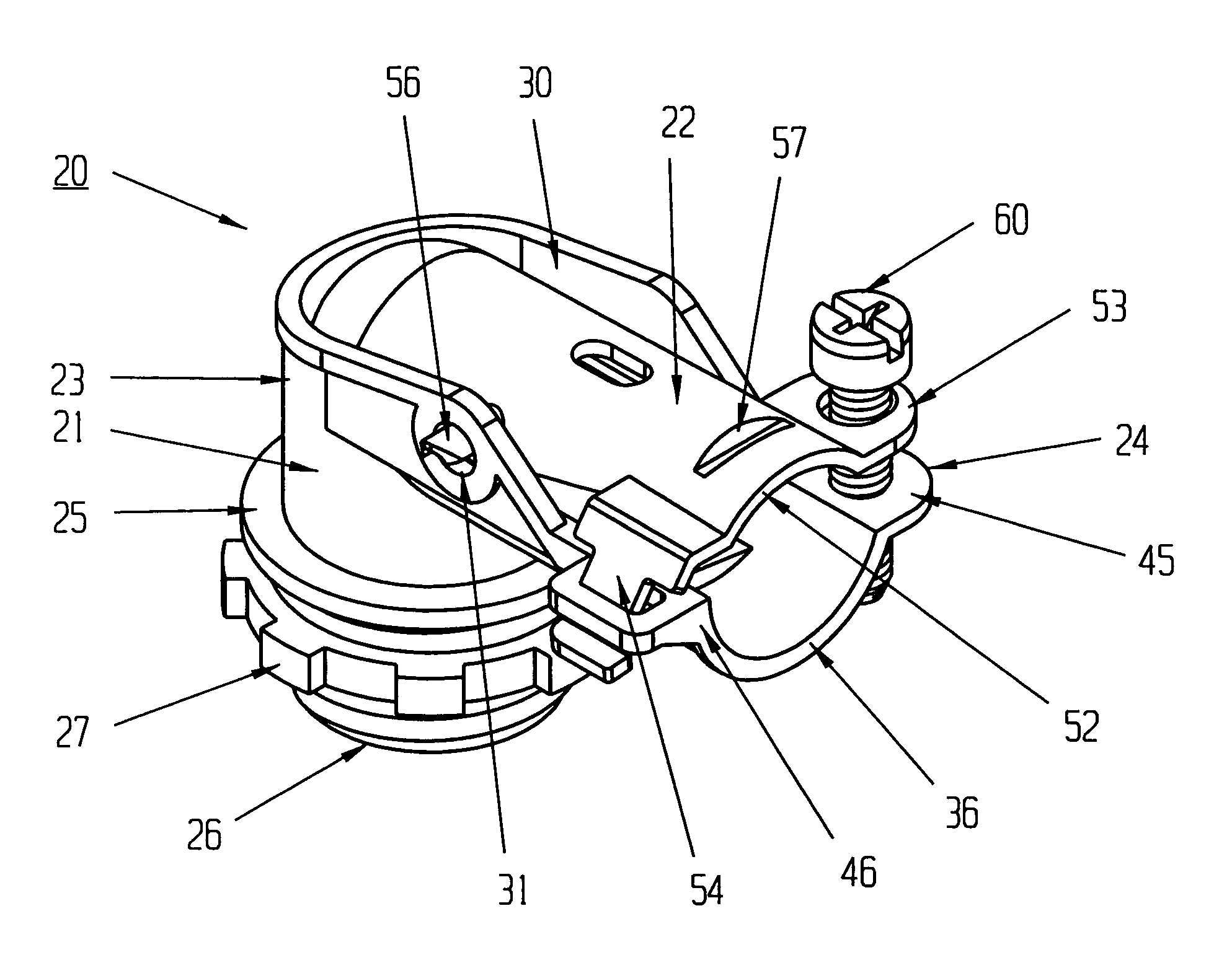
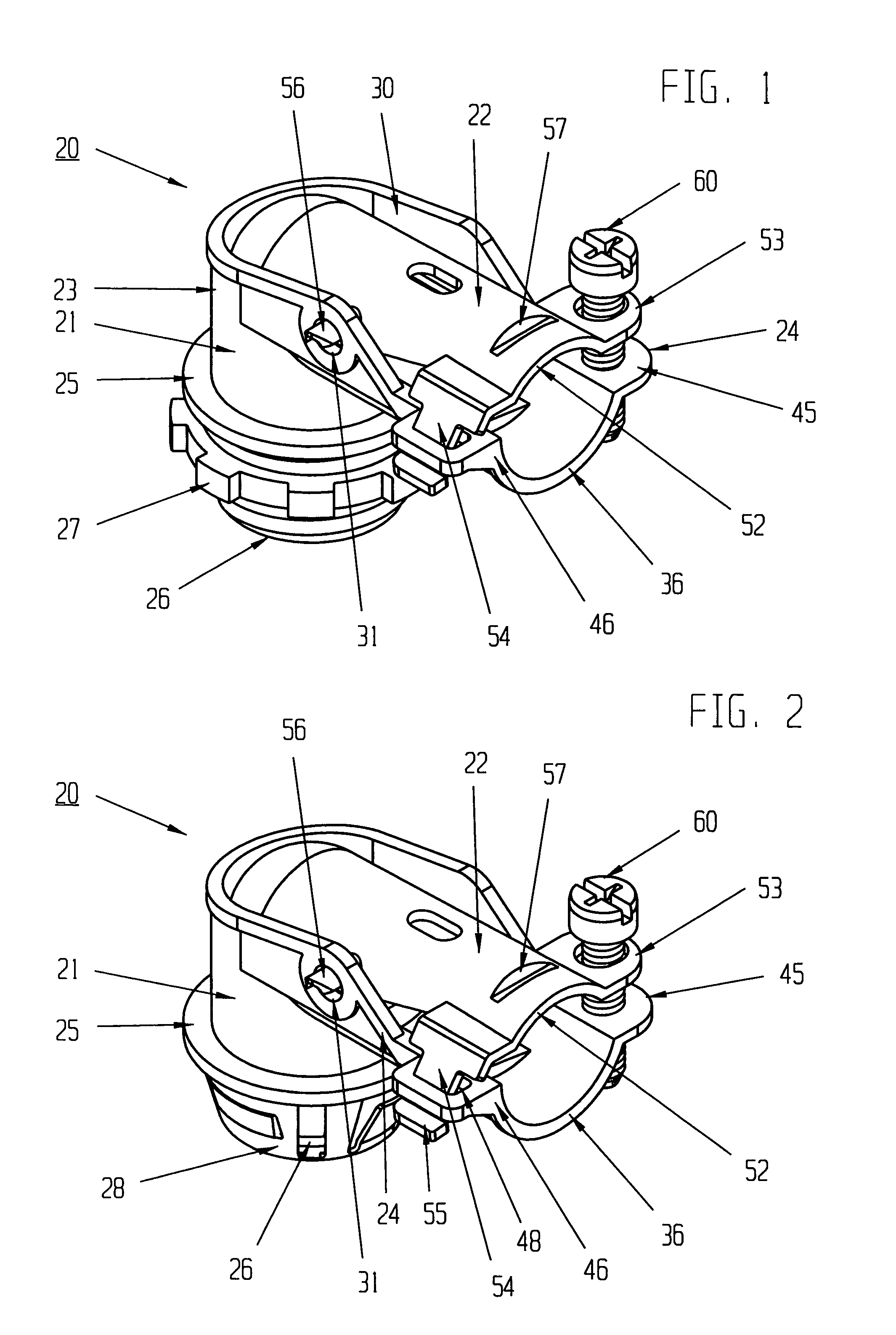
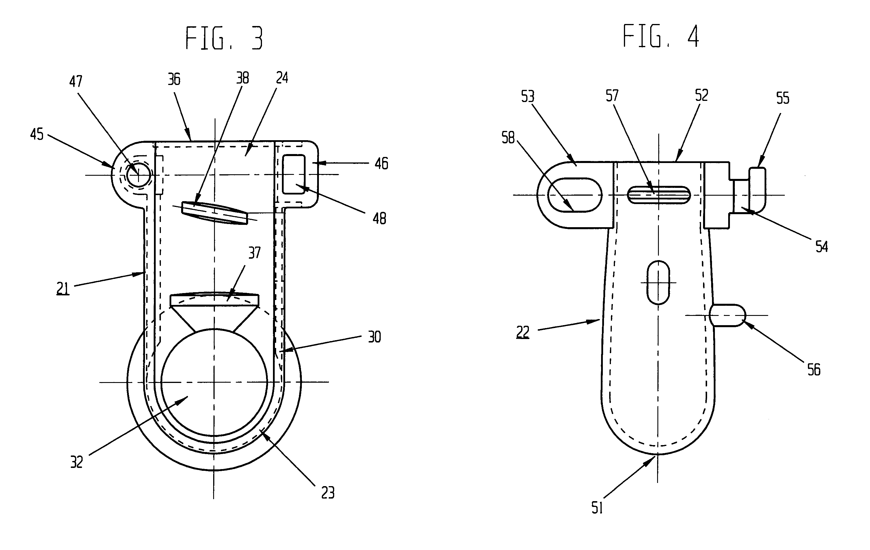
[0029]By referring to FIGS. 1–6, along with the following detailed discussion, the construction and use of conduit / cable connector 20 of the present invention can best be understood. In this regard, although two alternate embodiments of the present invention are depicted and detailed herein, further alternate embodiments of the present invention can be implemented without departing from the scope of the present invention. Consequently, it is to be understood that FIGS. 1–6, and the following detailed discussion, are provided for exemplary purposes only and are not intended as a limitation of the present invention.

[0030]As shown in FIGS. 1–6, both alternate embodiments of conduit / cable connector 20 incorporate base member 21 and cover portion or member 22. In the preferred construction, base member 21 incorporates substantially cylindrically shaped front section 23 and support plate 24 radially extending from and interconnected with cylindrically shaped front section 23. Furthermore,...


PUM


Abstract

By providing an integrated base member and cover member, with the cover member being easily arcuately pivotable along one edge and easily fastened to the base member along the opposed edge, an easily manufactured and easily assembled conduit/cable connector is realized. Furthermore, by employing the conduit/cable connector of the present invention, any desired flexible metal conduit and/or armored or metal clad cable is quickly and easily secured to the connector for mounting thereof to an outlet box or junction box at right angles, with complete assurance that the entire mounting operation can be achieved by a single operator quickly and easily.

Description

TECHNICAL FIELD[0001]This invention relates to electrical connectors, and more particularly, to electrical connectors constructed for securing flexible metal conduits and / or metal clad sheath cables to junction boxes and / or outlet boxes.[0002]In the field of wiring homes and buildings, whether for new construction or for improvements or expansion, substantial development and product improvements have been made. Typically, these improvements are directed to enabling installers to securely mount any desired wiring to any desired location in the most efficient and quickest manner.[0003]In any particular installation or location, various conduits or cables must be interconnected to each other as well as connected to the primary power supply in a suitable power distributing outlet box, junction box or other enclosure. In each of these instances, flexible metal conduits and / or armored or metal clad cables, within which the electrical power carrying wires are contained, must be securely mo...

Claims


Application Information

Patent Timeline
IPC IPC(8): H02G3/18
CPCH02G3/0683Y10T16/063
Inventor KIELY, KENNETH M.
Owner BRIDGEPORT FITTINGS LLC
Why Eureka
Try Eureka