Energy storage apparatus

a technology of energy storage and equipment, which is applied in the direction of electrical equipment, transformers/inductance details, transformers/inductance coils/windings/connections, etc., can solve the problems of affecting the manufacture of energy storage equipment, occupying a large space for the insulating layer on the stranded wires, and inconvenience in the process of winding wires and connecting printed circuit boards. , to achieve the effect of reducing the height of the coil,

Inactive Publication Date: 2017-04-27
CHICONY POWER TECH CO LTD
View PDF1 Cites 3 Cited by
  • Summary
  • Abstract
  • Description
  • Claims
  • Application Information

AI Technical Summary

Benefits of technology

[0010]Compared with the prior art, this disclosure has the following advantages and effects: The first coil and / or second coil are formed by perpendicularly winding a flat conductor to replace the coil composed of a plurality of stranded wires, so that the volume can be reduced. Since the coil is coupled to the pin portion, components can be inserted easily and quickly and connected to a printed circuit board by surface mount technology. In addition, the width and depth of each wire crossing slot are determined by the width and thickness of each passing pin, so that when each pin passes through each wire crossing slot and crosses each coil body, the top of each pin is substantially aligned with an edge portion of each coil body, so as to achieve the effect of reducing the height of the coil and reducing the overall volume of the components.

Problems solved by technology

However, if the current becomes larger, the number of stranded wires will be increased accordingly, and thus making the manufacture of the energy storage apparatus difficult.
In addition, the insulating layer covered onto the stranded wires also occupies some space.
The large volume causes inconvenience in the processes of winding wires and connecting printed circuit boards.
In addition, the process of winding wires for a plurality of coils is difficult and time-consuming.
Obviously, the increase of total height is not conducive to the reduction of the volume.

Method used


Image

  • Energy storage apparatus
  • Energy storage apparatus
  • Energy storage apparatus

Examples


first embodiment

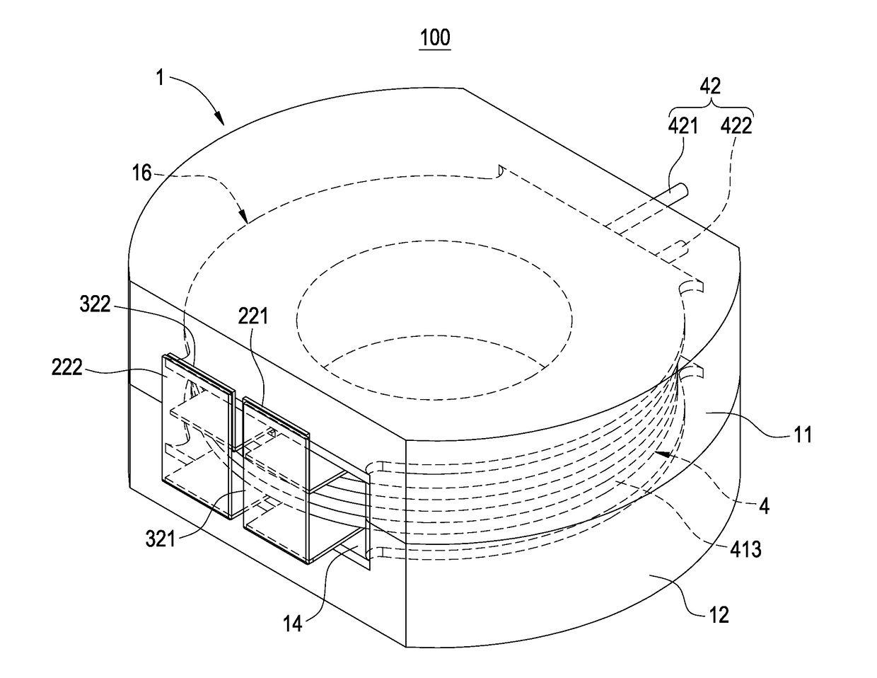
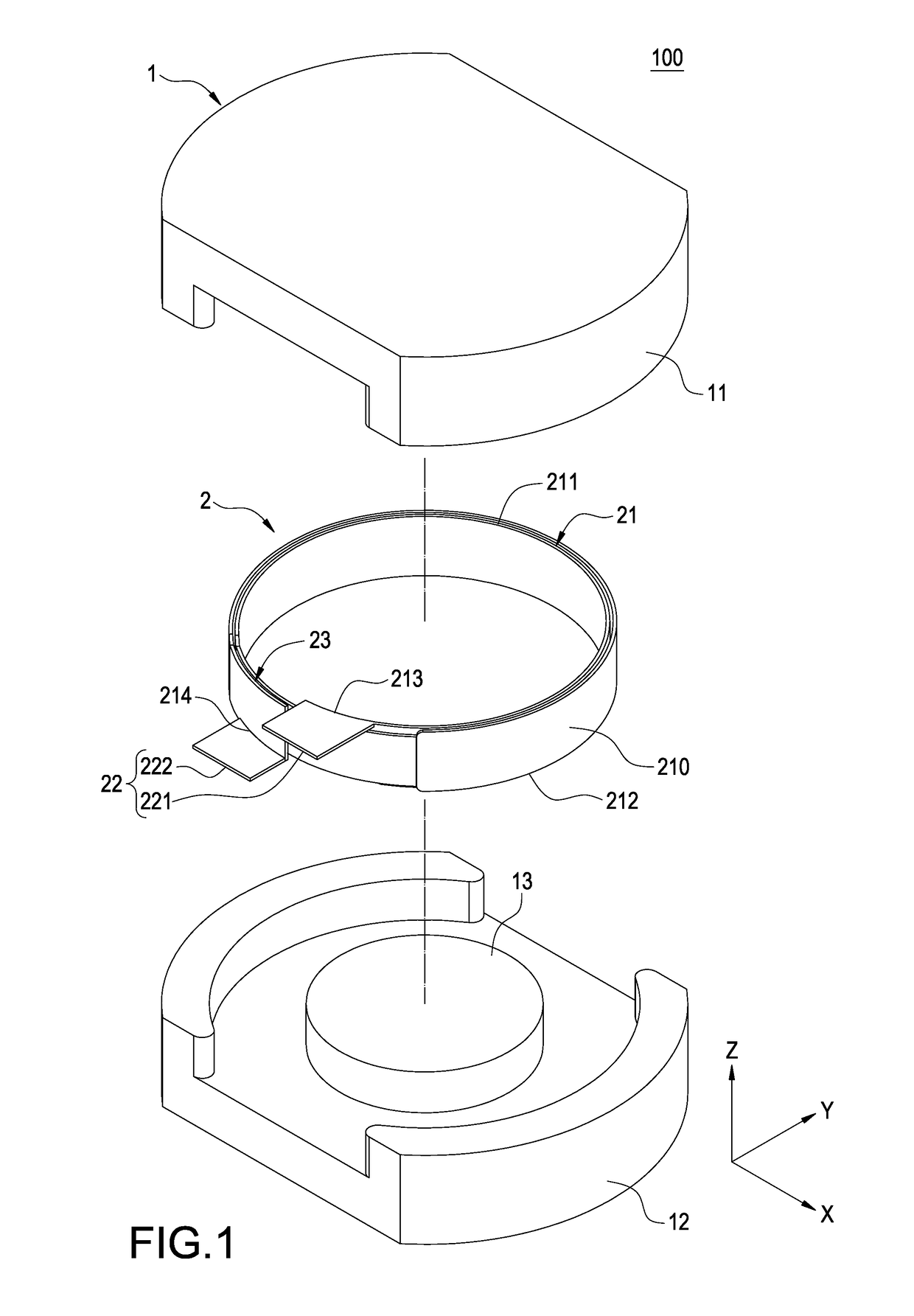
[0028]In this disclosure as shown in FIGS. 1˜3, an energy storage apparatus comprises a core 1 and a first coil 2.

[0029]The core 1 may be a single-component I Core (not shown in the figure) having no wire outlet, or a two-component E-E Core or RM Core having at least one wire outlet (as shown in FIGS. 1˜3), but this disclosure is not limited to the aforementioned arrangements only. In the figures, the core (E-E Core) has a first wire outlet 14 as shown in FIG. 3 and includes a first core 11 and a second core 12 engaged with one another.

[0030]The core 1 further includes a winding portion provided for winding a coil. In this embodiment, the core 1 has a first winding portion 13.

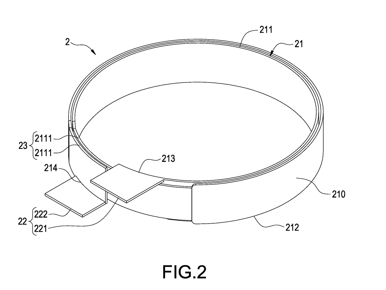
[0031]The first coil 2 includes a first coil body 21 and a first pin portion 22. Wherein, the first coil body 21 has a first inner end 213 and a first outer end 214, and the first pin portion 22 includes a first inner end pin 221 coupled to the first inner end213 and a first outer end pin 222 coupled to the fir...

third embodiment

[0058]Further, the structure of the third coil 4a is substantially the same as that of the third coil 3 of the third embodiment, except that the coil layer module just includes two coil layer arranged with an interval apart and adjacent to each other. The third pin portion 422a includes a third inner end pin 421a and a third outer end pin 422a coupled to the coil layer module.

[0059]An edge portion (such as an upper edge portion 211a or a lower edge portion 212a, and this embodiment uses the upper edge portion 211a for demonstration) of the first coil body 21a has at least one recess 2112a to form a third wire crossing slot 43a, and the first coil body 21a is disposed between two adjacent coil layers. Now, the third inner end pin 421a passes through the third wire crossing slot 43a and crosses the upper edge portion 211a of the first coil body 21a.

[0060]An edge portion of the first coil body 21a (such as the upper edge portion 211a or the lower edge portion 212a, and this embodiment...


PUM

PropertyMeasurementUnit
polarityaaaaaaaaaa
volumeaaaaaaaaaa
heightaaaaaaaaaa

Abstract

An energy storage apparatus includes a core and a first coil. The core has a winding portion, and the first coil includes a first coil body and a first pin portion. The first coil body is formed by winding a flat conductor around the winding portion perpendicularly and has a first inner end and a first outer end, and an edge of the first coil body has a notch to form a first wire crossing slot. The first pin portion includes a first inner end pin and a first outer end pin coupled to the first inner end and the first outer end respectively. The first inner end pin passes through a first wire crossing slot and crosses the first coil body to achieve the effects of reducing the overall volume and inserting components easily and quickly.

Description

FIELD OF THE INVENTION[0001]The technical field relates to an energy storage apparatus, more particularly to the energy storage apparatus capable of reducing the overall volume and inserting components easily and quickly.BACKGROUND OF THE INVENTION[0002]An energy storage apparatus may be an inductor having a single coil or a transformer having a plurality of coils, and most conventional coils are composed of a plurality of stranded wires to avoid the skin effect. However, if the current becomes larger, the number of stranded wires will be increased accordingly, and thus making the manufacture of the energy storage apparatus difficult.[0003]In addition, the insulating layer covered onto the stranded wires also occupies some space. The more the stranded wires, the larger volume of the coil. The large volume causes inconvenience in the processes of winding wires and connecting printed circuit boards. In addition, the process of winding wires for a plurality of coils is difficult and ti...

Claims


Application Information

Patent Timeline
Patent Type & Authority Applications(United States)
IPC IPC(8): H01F27/29H01F27/28
CPCH01F27/2823H01F27/292H01F27/2852H01F27/2866H01F27/306
Inventor LIU, CHIN-JENHO, TSUNG-HSUNHUANG, CHAO-JUI
Owner CHICONY POWER TECH CO LTD
Why Eureka
Try Eureka