RAM neutralization system and method

a neutralization system and ram technology, applied in the field of battlefield defense, can solve the problems of ram threat being extremely difficult to kill, ram threat requires large and sophisticated hardware, and ram threat can be destroyed in the blast, so as to achieve the effect of destroying or reducing ram threa

Inactive Publication Date: 2009-05-07
DESE RESEARCH
View PDF19 Cites 38 Cited by
  • Summary
  • Abstract
  • Description
  • Claims
  • Application Information

AI Technical Summary

Benefits of technology

[0009]The present invention recognizes and addresses various of the foregoing limitations and drawbacks, and others, regarding RAM intercept and neutralization systems and methods. Therefore, the present invention is directed to a RAM neutralization system and method that has a relaxed guidance precision requirement and provides more opportunity to destroy or mitigate the RAM threat.
[0013]It is, therefore, a principle object of the subject invention to provide a cost-effective RAM neutralization system and method. More particularly, it is an object of the present invention to provide a RAM neutralization system and method that does not necessarily require high guidance precision. It is another object of the invention to provide for expanded options for destroying or mitigating the RAM threat. It is a further object of the invention to minimize the collateral damage associated with neutralizing a RAM threat.

Problems solved by technology

A RAM threat is an extremely difficult target to kill.
Moreover, many interceptors utilize warheads to kill the RAM threat and thus require large and sophisticated hardware.
For example, the interceptor may incorporate an explosive warhead that detonates when the interceptor is in close proximity to the RAM, destroying the RAM in the blast.
Even when an interceptor hits a RAM, it is extremely difficult to disable or destroy the RAM.
Unfortunately, in some circumstances when a RAM is “killed”, shrapnel or debris from the RAM or the interceptor may still cause collateral damage.
Thus the success of the battle is often decided by economics—the cost and size of the interceptor and supporting fire control components are very high making the cost per RAM kill unacceptable.
Indeed, as the acceptable miss distance of a particular intercept system (i.e., how close the interceptor must come to the RAM to enable it to destroy or disable the RAM) decreases, the cost of the intercept system goes up exponentially due to the complexity and sophistication of the guidance componentry.
The enemy's ability to proliferate the low-cost, low complexity RAM threat easily counters a defense capability that is complex and expensive.

Method used


Image

  • RAM neutralization system and method
  • RAM neutralization system and method
  • RAM neutralization system and method

Examples


Embodiment Construction

[0029]Reference will now be made in detail to presently preferred embodiments of the invention, examples of which are fully represented in the accompanying drawings. Such examples are provided by way of an explanation of the invention, not limitation thereof. In fact, it will be apparent to those skilled in the art that various modifications and variations can be made in the present invention, without departing from the spirit and scope thereof. For instance, features illustrated or described as part of one embodiment can be used on another embodiment to yield a still further embodiment. Still further, variations in selection of materials and / or characteristics may be practiced, to satisfy particular desired user criteria. Thus, it is intended that the present invention cover such modifications and variations as come within the scope of the present features and their equivalents.

[0030]As disclosed above, the present invention is particularly concerned with a RAM neutralization syste...


PUM


Abstract

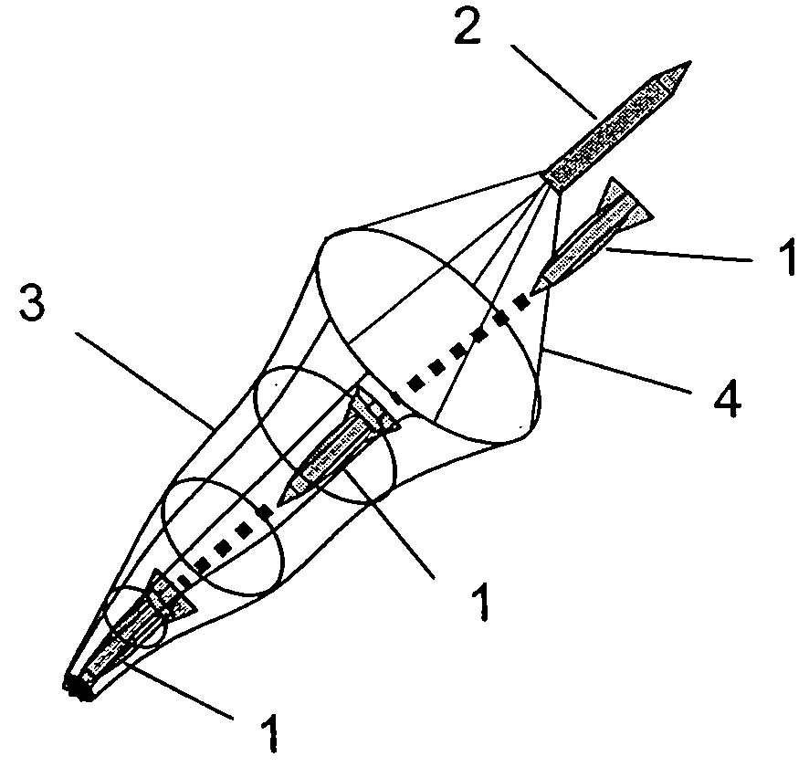
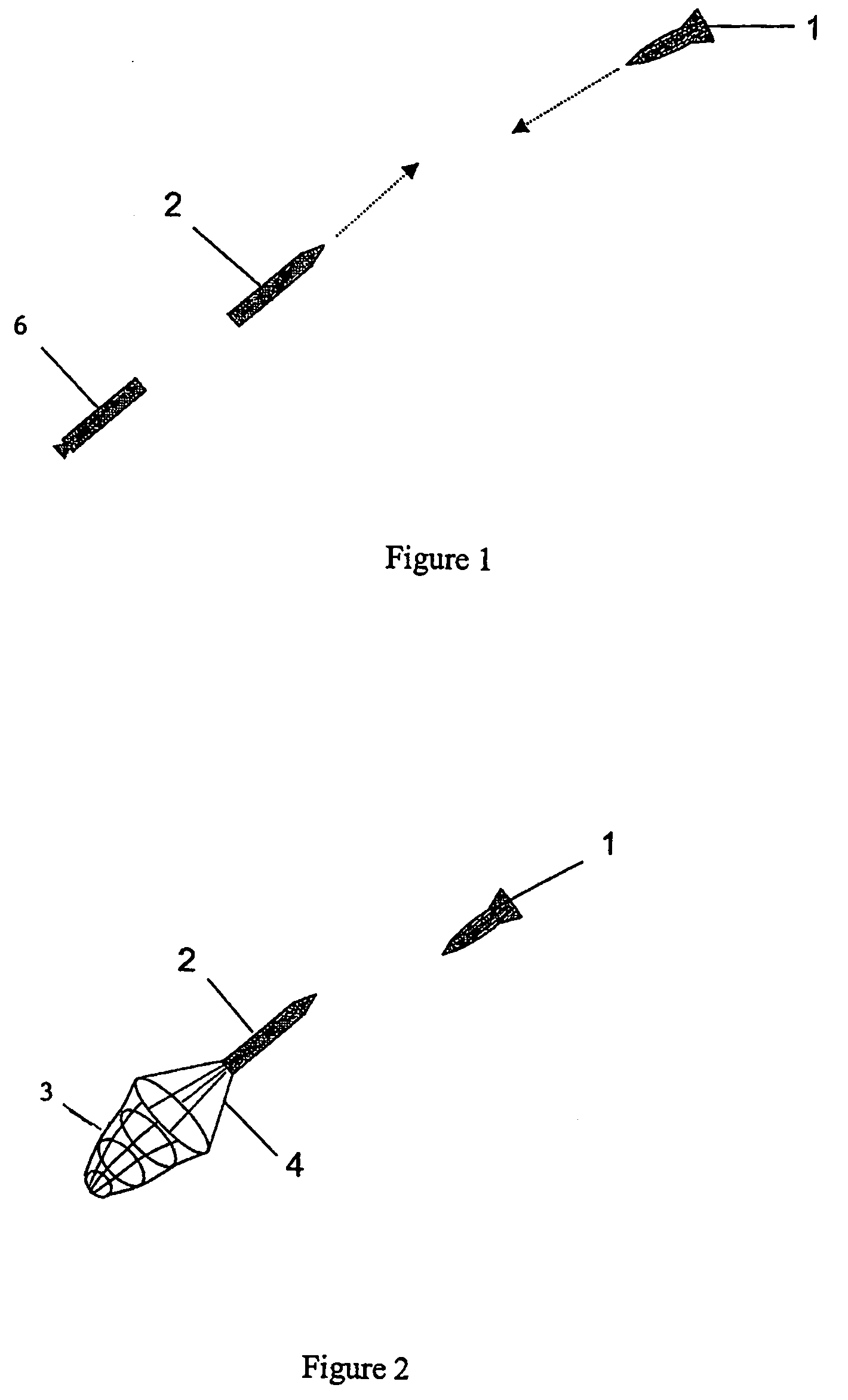
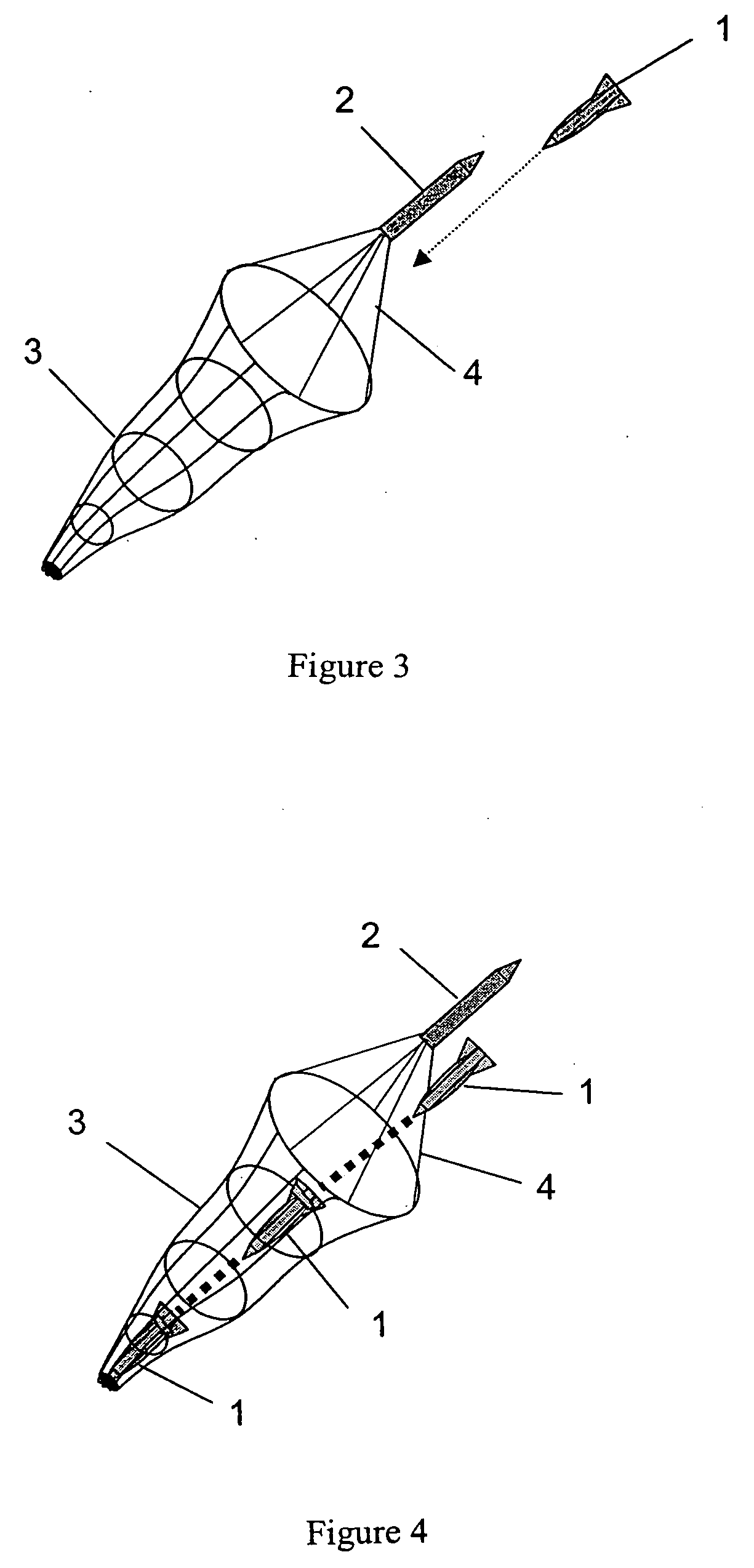
An article for neutralizing an enemy weapon comprising an interceptor and a deployable net attached to the interceptor, said deployable net remaining attached to the interceptor upon deployment is disclosed. A method of neutralizing an airborne enemy weapon comprising launching an interceptor, with a capture sock, towards the enemy weapon and deploying the capture sock just prior to the interceptor encountering the enemy weapon is also disclosed. The capture sock remains attached to the interceptor upon deployment.

Description

BACKGROUND OF THE INVENTION[0001]This invention generally relates to a system and method for intercepting rockets, artillery, and mortar for battlefield defense. In particular, the present invention relates to a method and system for neutralizing rockets, artillery, and mortars using a capture sock or net.[0002]Historically, the greatest killer on the battlefield has been rockets, artillery, and mortar, often collectively referred to as RAM. A RAM threat is an extremely difficult target to kill. Using conventional interceptor technology, the interceptor is required to utilize high precision guidance systems to guide the interceptor accurately enough to hit the threat. Moreover, many interceptors utilize warheads to kill the RAM threat and thus require large and sophisticated hardware.[0003]Various guidance systems for interceptors are well-known in the industry. Generally, guidance systems are either “passive”, “active”, or a combination of “active” and “passive.” Passive systems ge...

Claims


Application Information

Patent Timeline
Patent Type & Authority Applications(United States)
IPC IPC(8): F42B15/00B64D17/00F42B12/20
CPCF41H11/02F42B12/68F41H13/0006
Inventor SELLS, II, HAROLD R.
Owner DESE RESEARCH
Why Eureka
Try Eureka