Flexible battery container and method of use

a battery container and flexible technology, applied in the field of flexible bodies, can solve the problems of power supply, battery power loss, and full discharge of portable devices,

Inactive Publication Date: 2009-05-21
GROSSMAN VICTOR A
View PDF11 Cites 20 Cited by
  • Summary
  • Abstract
  • Description
  • Claims
  • Application Information

AI Technical Summary

Benefits of technology

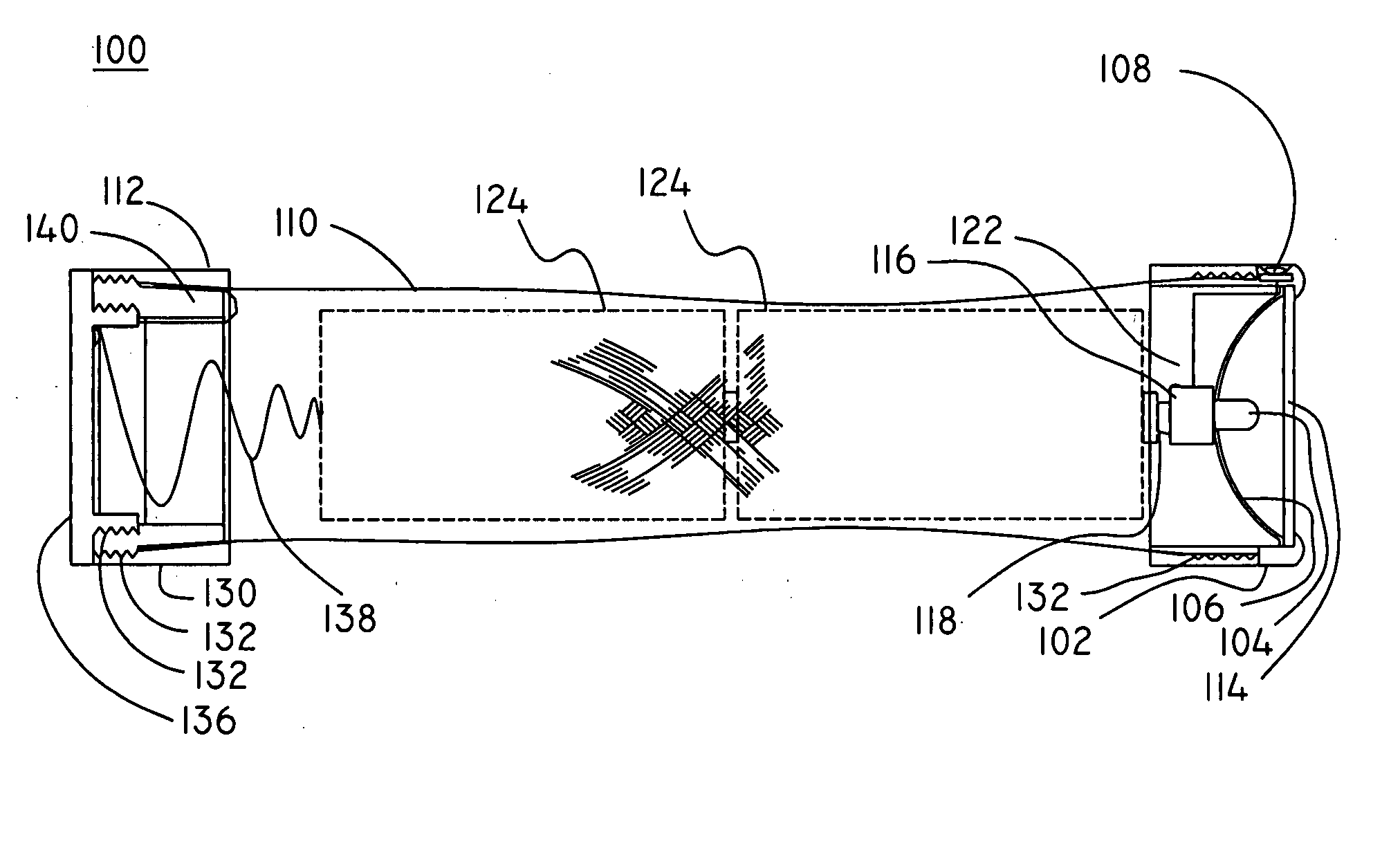
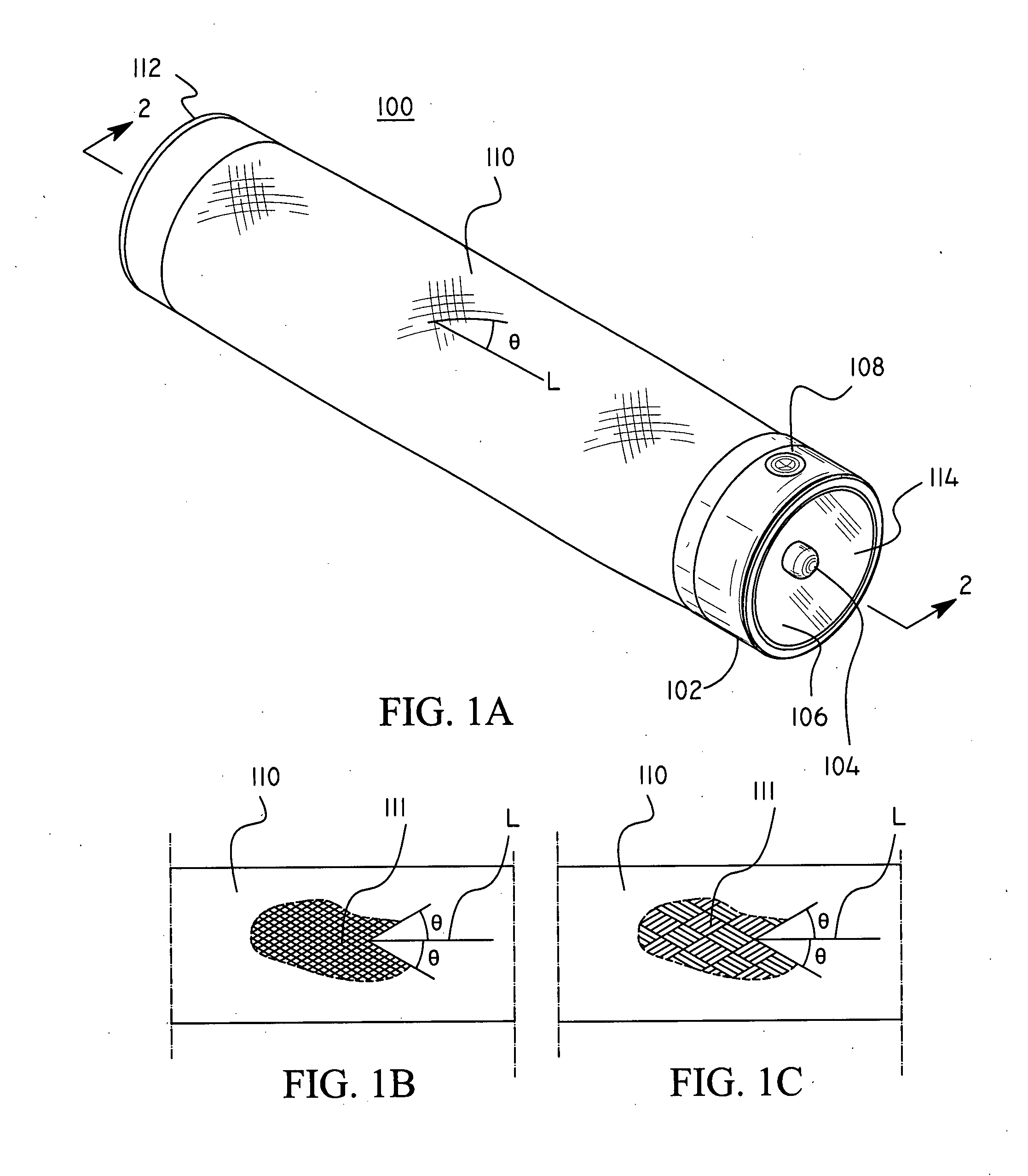
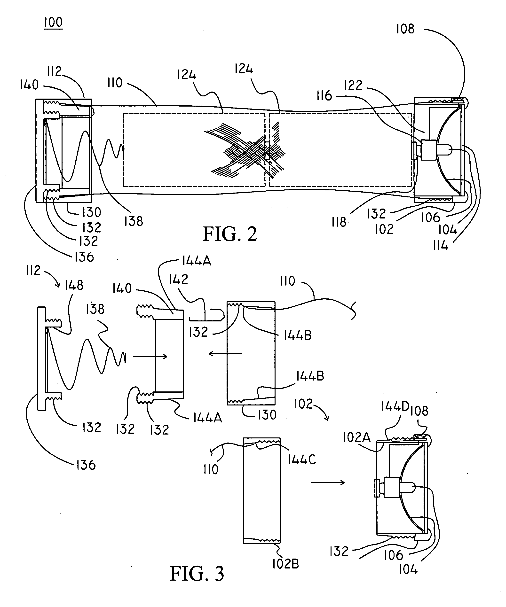
[0015]It is another aspect of the present invention to provide a flashlight apparatus, including a body part formed from a woven material for forming an adjustable cavity, the adjustable cavity being adjustable in diameter and / or length, such that a desired number of battery cells or battery cells having a different type can be located by the body part. The body part optionally conducts current from the battery cells. A head part is connected to the body part and includes one or more illumination sources for providing illumination. The size and / or shape of an inner cavity of the body portion can be changed so that batteries contained therein are held in a desired position. Further, a clamp may be provided to adjust the size and / or shape of the inner cavity. An optional length adjusting member may be used to locate a terminal of an adjacent battery in a desired position. An optional biasing element may be used to provide a biasing force against a terminal of an adjacent battery and / or the body part.
[0016]The body is formed from a woven material. The woven material is preferably formed from a polymer. The woven material may optionally include electrically conductive and / or optically conductive strands. The body may be optionally formed from a metal such as brass, aluminum, copper, or combinations thereof. An optical couple can be provided to optically couple the conductive strands to the illumination source and / or another illumination source. The illumination sources may include light-emitting diodes (LEDs), laser LEDs, incandescent bulbs, and fluorescent bulbs, electroluminescent (EL) elements, etc. The head portion may include a sheet of material such as a metallic or polymeric material, and / or may include one or more weakened lines. The head portion may include an LED.

Problems solved by technology

However, these devices require a power supply.
However, even with the most diligent attempts, portable devices may run low or out of battery power (i.e., become fully discharged) in which case there is need to either charge or replace their batteries at inconvenient locations or times. Thus, while a user may conventionally use a power outlet to power and / or charge these mobile devices (e.g., mobile phones), this may not be possible when outdoors, in an area that lacks a power supply, or during a power failure.
However, they do not check the batteries of these devices on a regular basis.
Accordingly, during a power failure, or other emergency (e.g., a national disaster, terrorist attack, etc.) when, for example, flashlight use is typically required, a flashlight that is capable of supplying light may not be available because of discharged or run-down batteries.
Although soldiers typically carry expected gear such as these mobile devices (e.g., flashlights, communication devices, etc.) and supplies of fully-charged batteries on their person or have this gear supplied, this may not always be the case.
For example, existing rigid-body mobile devices such as flashlights occupy a great deal of space and it may be difficult or impossible for soldiers to charge existing batteries or to obtain a required number and type of battery for these mobile devices when their batteries run low, are damaged, or become discharged.
Accordingly, their lives and mission may be placed at risk because of the lack of battery power.
However, with the lack of power, these devices would be rendered useless and the soldier's life may be placed at risk.
However, if the flashlights batteries are discharged, the flashlight may not be capable of providing the necessary illumination.

Method used


Image

  • Flexible battery container and method of use
  • Flexible battery container and method of use
  • Flexible battery container and method of use

Examples


Embodiment Construction

[0062]Preferred embodiments of the present invention will be described in detail with reference to the annexed drawings. In the following description, a detailed description of known functions and configurations incorporated herein will be omitted when it may obscure the subject matter of the present invention.

[0063]Note that throughout the present invention, interchangeability of components is contemplated and the corresponding terms throughout this specification including the claims may therefore be substituted for one another as desired as would be reasonable to one skilled in the art. For example, a light emitting diode (LED) may be substituted for an incandescent bulb. Likewise the flexible battery holder may be attached to another device (e.g., a cellular phone, a PDA, a battery charger, a USB port, etc.) for providing power to and / or receiving power from (e.g., in the case of the battery charger) the other device. Power sources used in the present invention may include batter...


PUM

PropertyMeasurementUnit
output voltageaaaaaaaaaa

Abstract

A flashlight apparatus including a body portion formed from a woven material, the body portion having a longitudinal length and forming at least part of an adjustable cavity for containing at least one battery, and a head portion coupled to the body portion and having at least one of an illumination source for providing illumination and a connector for connecting the flashlight to another device. Accordingly, the flashlight can supply power to the another device. The body portion can adjust (e.g., its length and diameter—or area) to the size and number of battery cells contained therein.

Description

FIELD OF THE INVENTION[0001]The present invention relates generally to a flexible body for accepting battery cells, and more particularly to a flexible body for a battery pack, a flashlight, or other devices, which can accept batteries of various numbers and types.BACKGROUND OF THE INVENTION[0002]With the recent progress of technology, mobile (i.e., portable) devices have become commonplace. However, these devices require a power supply. Typically, a user can determine when to charge or replace a battery to avoid the inconvenience of running low on batteries. For example, users of portable devices, such as mobile phones, typically charge their mobile phones when at home, work, etc., so that they do not inadvertently run low on power when using the devices in a mobile environment. To this effect, mobile devices typically include a battery power meter for indicating a charged state.[0003]However, even with the most diligent attempts, portable devices may run low or out of battery powe...

Claims


Application Information

Patent Timeline
Patent Type & Authority Applications(United States)
IPC IPC(8): F21L4/00H01M14/00
CPCF21L4/027F21Y2101/02Y02E60/50H01M8/2475H01M2/1055F21Y2101/00F21Y2115/10H01M50/213Y02E60/10
Inventor GROSSMAN, VICTOR A.
Owner GROSSMAN VICTOR A
Why Eureka
Try Eureka