
Dovetail attachment for use with turbine assemblies and methods of assembling turbine assemblies
- Summary
- Abstract
- Description
- Claims
- Application Information
AI Technical Summary
Benefits of technology
Problems solved by technology
Method used
Image

Examples
Embodiment Construction
[0013]At least one embodiment of the present invention is described below in reference to its application in connection with and operation of a steam turbine engine. Further, at least one embodiment of the present invention is described below in reference to a nominal size and including a set of nominal dimensions. However, it should be apparent to those skilled in the art and guided by the teachings herein provided that the invention is likewise applicable to any suitable turbine and / or engine. Further, it should be apparent to those skilled in the art and guided by the teachings herein provided that the invention is likewise applicable to various scales of the nominal size and / or nominal dimensions.
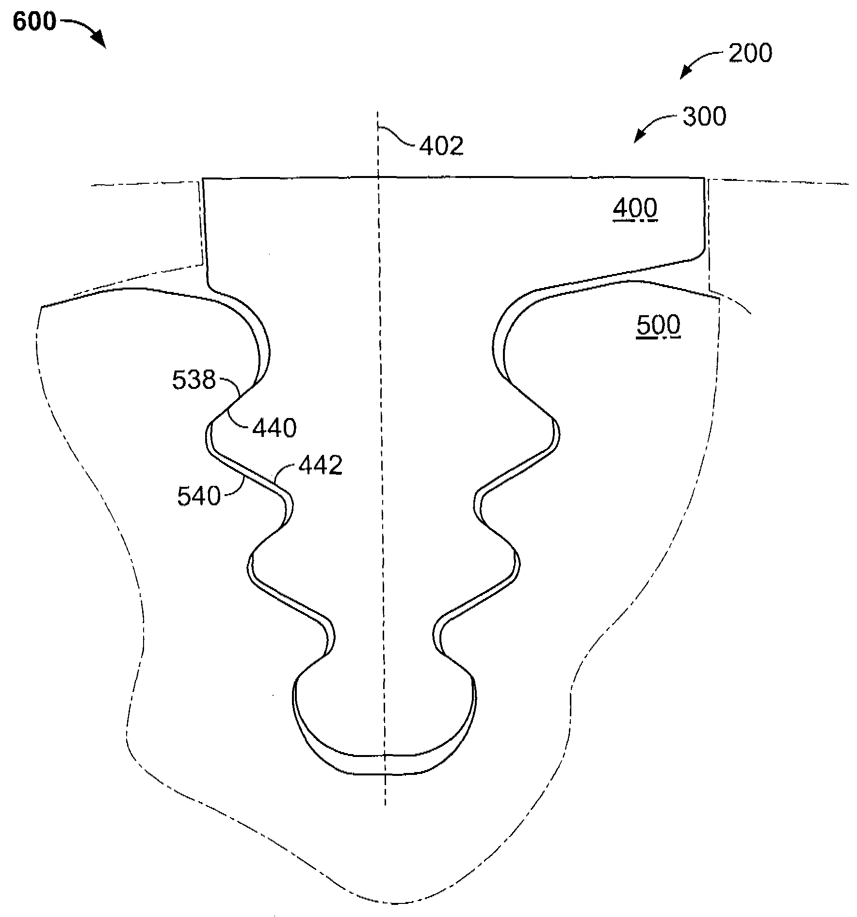
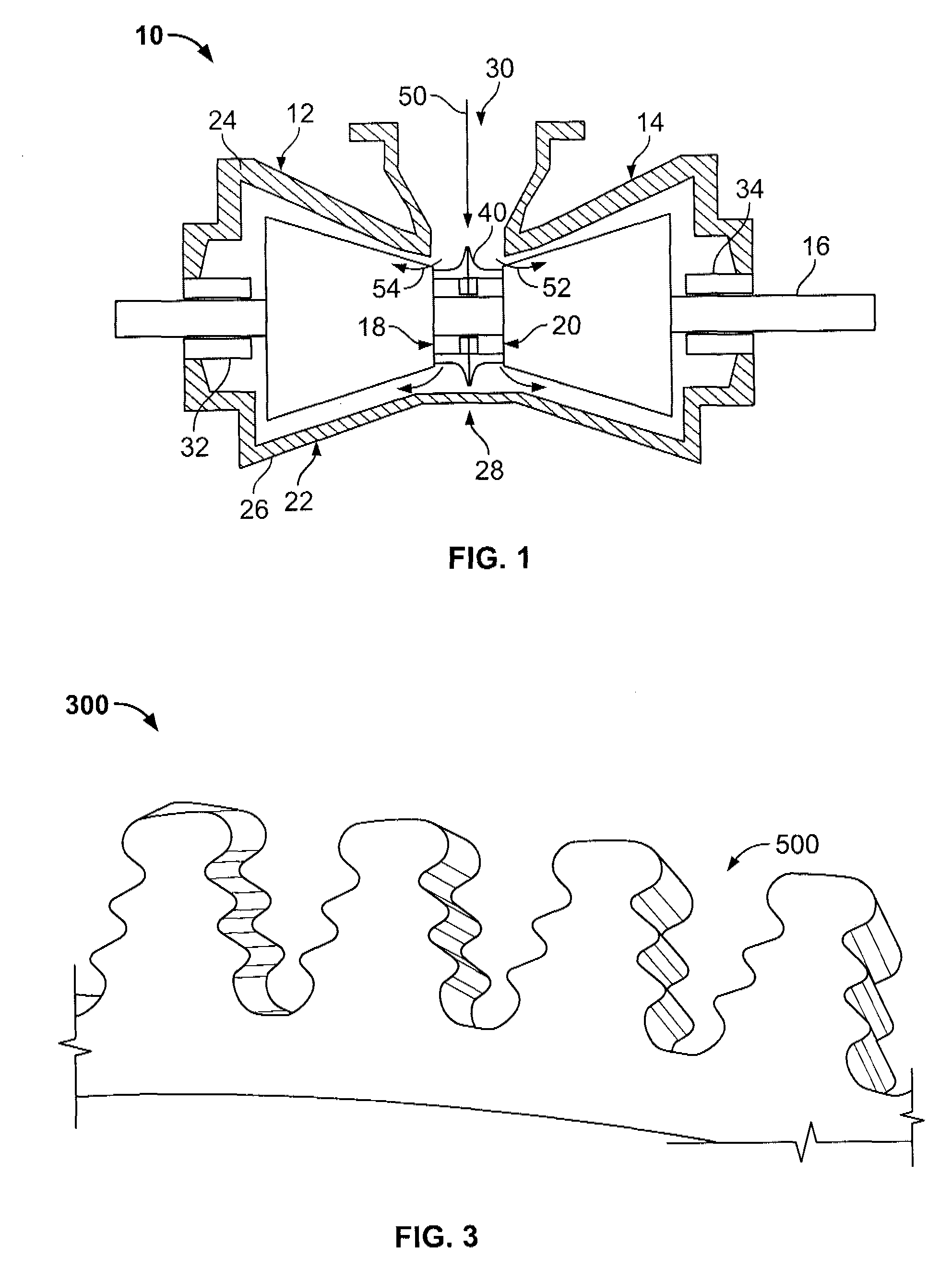
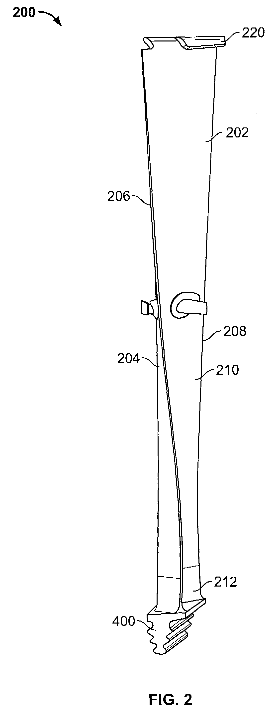
[0014]FIG. 1 is a schematic illustration of an exemplary opposed-flow steam turbine 10. Turbine 10 includes first and second low pressure (LP) sections 12 and 14. As is known in the art, each turbine section 12 and 14 includes a plurality of stages of diaphragms (not shown in FIG. 1). A...
PUM
| Property | Measurement | Unit |
|---|---|---|
| Angle | aaaaa | aaaaa |
| Length | aaaaa | aaaaa |
| Thickness | aaaaa | aaaaa |
Abstract
Description
Claims
Application Information