
Method and device for operating power semiconductor switches connected in parallel

Inactive Publication Date: 2017-11-16
ROBERT BOSCH GMBH
View PDF2 Cites 2 Cited by
  • Summary
  • Abstract
  • Description
  • Claims
  • Application Information

AI Technical Summary

Benefits of technology

The patent text describes a method and system for operating power semiconductor switches connected in parallel. By using total gate series resistors, each switch can be individually loaded based on its properties, allowing for greater tolerance and yield, and simplified testing and manufacturing processes. The system can also connect switches of different power classes or chip areas, avoiding overloading of weaker components. The overall device scalability is improved. The technical effects of this patent are improved performance, reliability, flexibility, and cost reduction for power semiconductor switch systems.

Problems solved by technology

Upper limits of current are predefined for said power semiconductor switches, the power semiconductor switches being damaged irreversibly in the event of said upper limits being exceeded.
This can have the effect that the current flow between the switches is divided unequally and individual power semiconductor switches are thus thermally loaded to a greater extent and thus fail more rapidly.

Method used


Image

  • Method and device for operating power semiconductor switches connected in parallel
  • Method and device for operating power semiconductor switches connected in parallel
  • Method and device for operating power semiconductor switches connected in parallel

Examples


Embodiment Construction

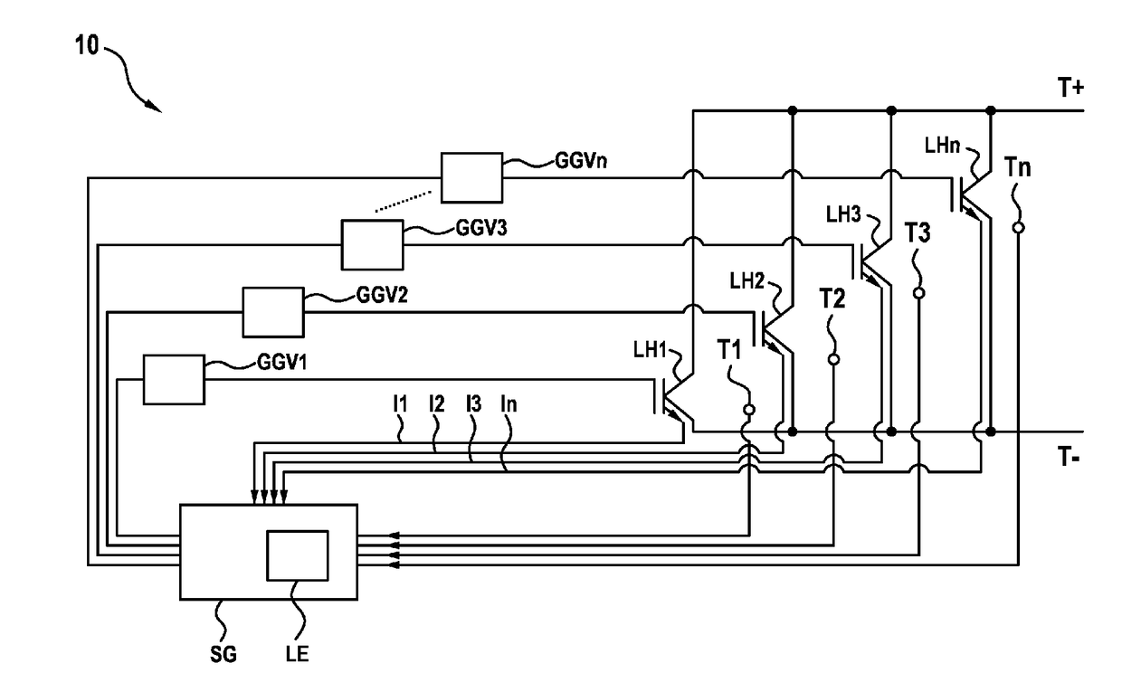
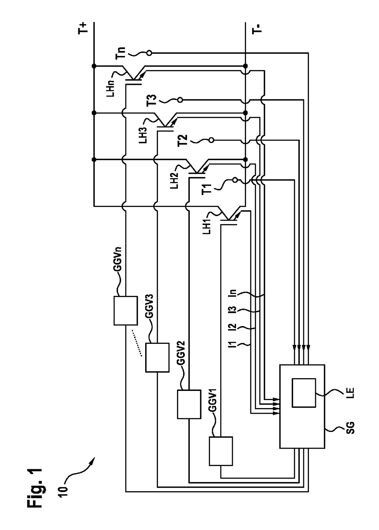
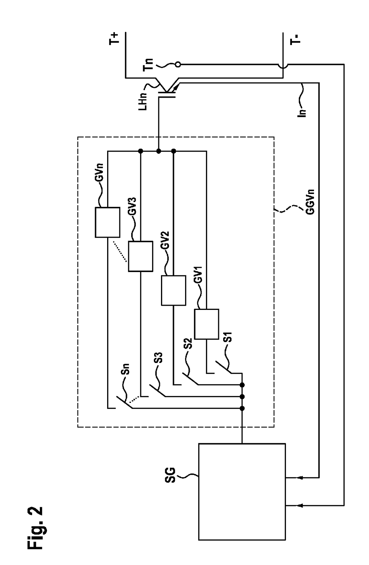
[0044]FIG. 1 shows an electrical system 10 in a schematic illustration. The electrical system 10 comprises power semiconductor switches LH1, LH2, LH3 . . . LHn, which are connected in parallel and conduct an electric current from the potential T+to the potential T− in the closed state and isolate the potentials in the open state. The gate terminals of the power semiconductor switches LH1 . . . LHn are connected to the respective total gate series resistors GGV1, GGV2, GGV3 . . . GGVn. Furthermore, a control device SG is provided, which is connected via the individual total gate series resistors GGV1 . . . GGVn to the individual gate terminals of the power semiconductor switches LH1 . . . LHn. By applying a voltage by means of voltage source (not illustrated) at the gate terminals of the power semiconductor switches LH1 . . . LHn, the power switches are controlled or a current flow through them is made possible; by removing or disconnecting the voltage at the gate terminals of the po...


PUM


Abstract

The invention relates to a method (100) and a control device (SG) for operating power semiconductor switches (LH1 . . . LHn) connected in parallel, having the following steps: determining a nominal value for a total gate series resistor (GGVL . . . GGVn) of at least one power semiconductor switch (LH1 . . . LHn); providing the total gate series resistor (GGV1 . . . GGVn) for the at least one power semiconductor switch (LH1 . . . LHn) depending on the relevant nominal value, and operating the at least one power semiconductor switch (LH1 . . . LHn) with the associated total gate series resistor (GGV1 . . . GGVn).

Description

BACKGROUND OF THE INVENTION[0001]The invention relates to a method and a control device for operating power semiconductor switches connected in parallel. Furthermore, the invention relates to an electrical circuit, an electrical system comprising the control device, a computer program for carrying out said method, and a machine-readable storage medium.[0002]Inverters are usually used for operating electrical drives, said inverters converting the electrical energy from a DC voltage source, e.g. a battery, into an AC voltage, in order to supply an electrical machine, e.g. an asynchronous machine, with AC voltage or AC current. The inverter has so-called half-bridges for this purpose. Said half-bridges have power semiconductor switches, by means of which the DC current and the DC voltage are switched in a clocked fashion, such that an AC voltage and an AC current arise at the output terminals of the inverter. Upper limits of current are predefined for said power semiconductor switches,...

Claims


Application Information

Patent Timeline
IPC IPC(8): H03K17/0812H02M7/537H03K17/12H02M7/493H03K17/08
CPCH03K17/0812H02M7/493H03K17/12H02M7/537H03K2017/0806H03K17/127
Inventor KILB, JOCHENALDINGER, STEFANRICHTER, TOBIAS
Owner ROBERT BOSCH GMBH
Learn More