Mop Press

Inactive Publication Date: 2011-03-10
CARL FREUDENBERG KG
View PDF11 Cites 2 Cited by
  • Summary
  • Abstract
  • Description
  • Claims
  • Application Information

AI Technical Summary

Benefits of technology

[0005]In an embodiment, a support device is provided on the housing and it is at a horizontal distance from the fastening mechanism. Here, the support device is at a greater distance from the fastening mechanism than in the case of the familiar vertical arrangement. In the configuration according to the invention, this distance is more than 150 mm, as a result of which the torque generated by the pressing procedure is reduced to smaller bearing forces. Part of the force applied to the wringing device is dissipated via the support device. Since the support device is horizontally at a distance from the fastening mechanism, the mop press is supported at several points so that the mop press can be affixed to a mop bucket or to a cleaning trolley very firmly. Via the lever, high forces can be applied to the wringing device and these forces are reliably transmitted via the fastening mechanism and the support device, thereby improving the handling and the wringing performance. The support device can also be offset vertically, but it is essential for the support device to be at a horizontal distance from the fastening mechanism.
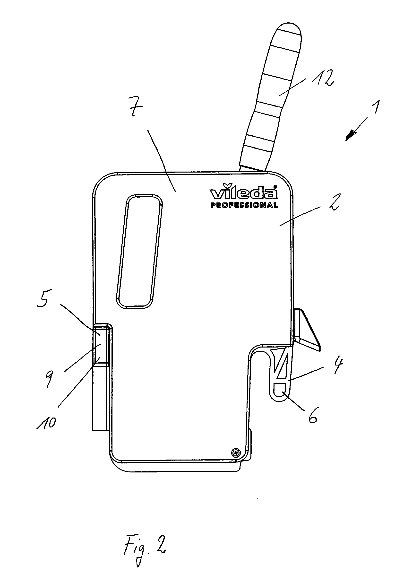
[0006]The fastening mechanism can consist of a hook-shaped projection. As a result, the mop press can be affixed especially easily onto a mop bucket or a cleaning trolley, and also removed again. All that is necessary is to hang the mop press in place.
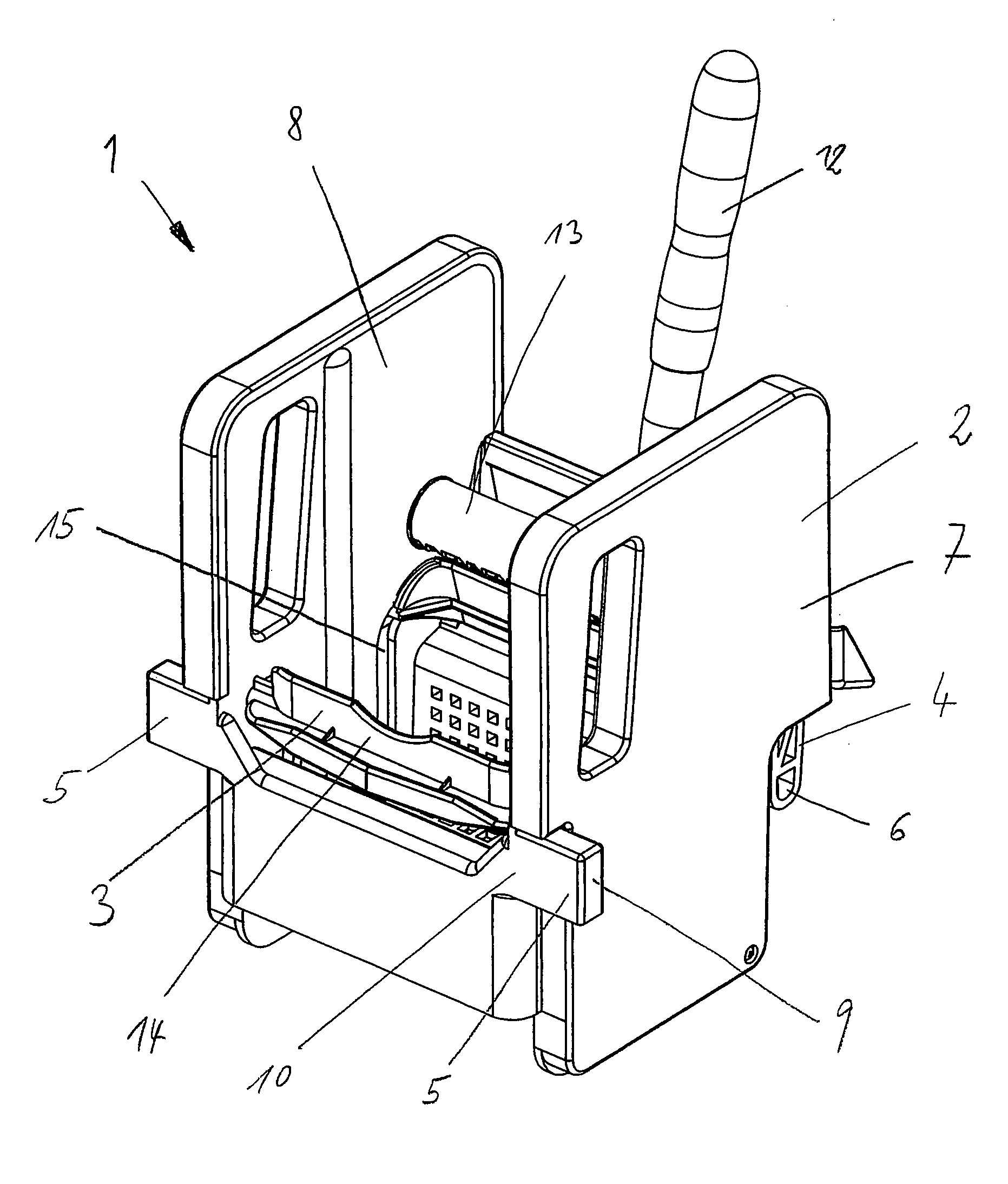
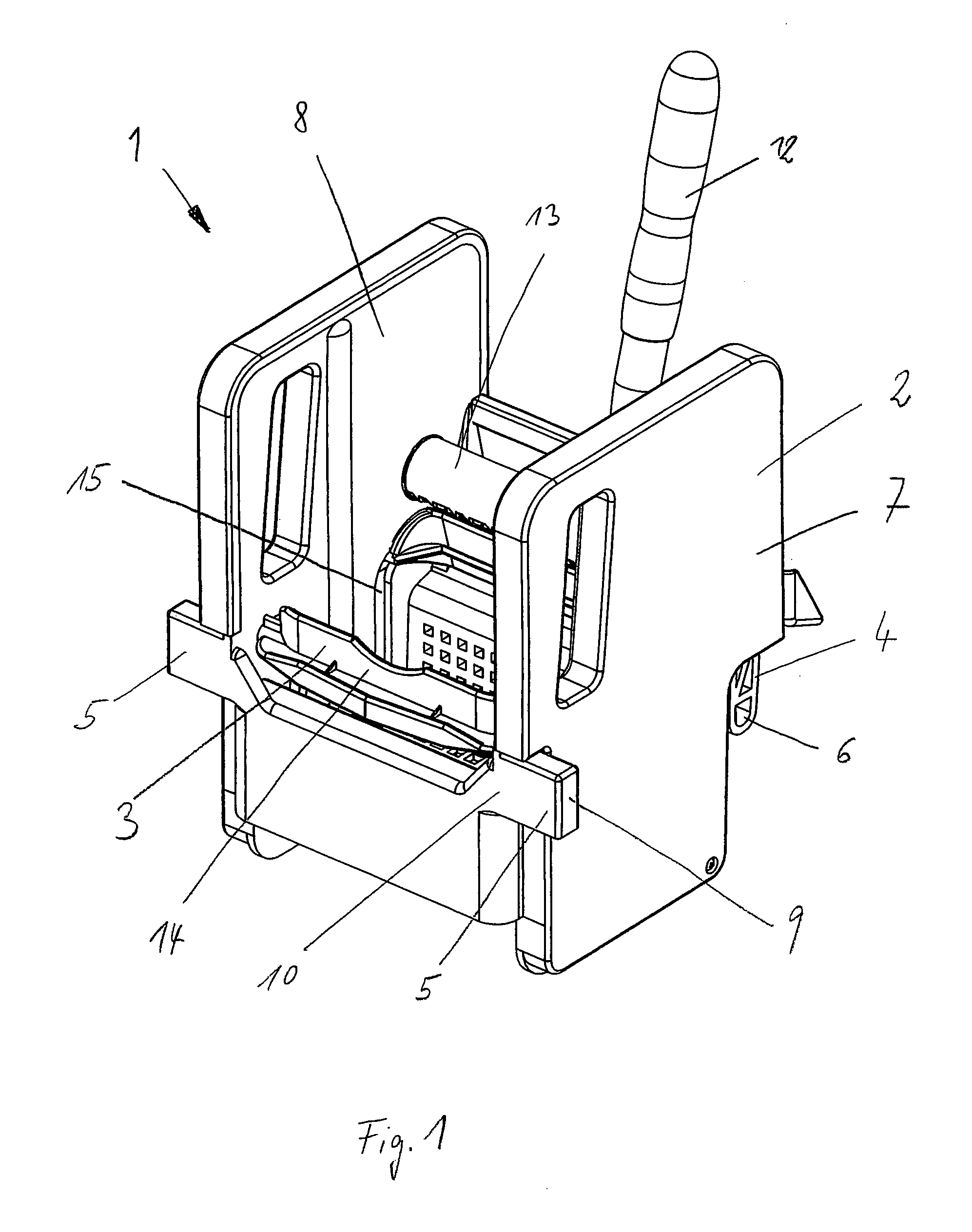
[0008]Each side panel can have a fastening mechanism on the rear. Here, the fastening mechanism can be shaped onto the side panels and can be manufactured together with them. Consequently, the fastening mechanism can be integrated especially easily into the mop press.
[0010]The housing can have at least one projection that extends laterally, that protrudes beyond the housing and that forms the support device. This projection can likewise be integrated into the side panel and can be shaped onto it. However, the projection can also be a separate component. Since the projection is arranged on the side opposite from the fastening mechanism, the result is a sturdy support of the torques due to the large support width, along with easy production and compact dimensions.
[0012]The side panels can have a projection, and they form the support device. Here, the support device is made of a single material in one piece with the side panel, as a result of which it is especially easy to manufacture.
[0013]The projection can extend from the front to the back of the side panel. In this embodiment, the support is uniform along the side panel, resulting in a uniform load on the mop bucker or cleaning trolley.

Problems solved by technology

If an excessive force if applied via the lever, the mop press can become detached from the fastening mechanism.

Method used


Image

  • Mop Press
  • Mop Press
  • Mop Press

Examples


Embodiment Construction

[0021]FIG. 1 shows a mop press 1 for wringing liquids out of a cleaning device, comprising a housing 2 consisting essentially of two side panels 7, 8 at a distance from each other, between which a lever-actuated wringing device 3 is arranged. The wringing device 3 comprises a lever 12 that opens up into a shaft 13, whereby the shaft 13 is supported in the side panels 7, 8. Within the side panels 7, 8, there is a gear arrangement via which the shaft 13 is connected to the pressing bars 14. These pressing bars 14 are guided in a connecting link 15 and, as a result, follow a curved path. In the housing 2, there is a rear fastening mechanism 4 for affixing the mop press to a mop bucket 16 or to a cleaning trolley 17. The fastening mechanism 4 consists of a hook-shaped projection 6 that is affixed directly to the wringing device 3. For stiffening purposes, the projection 6 is provided with ribs. There is such a projection 6 on each side, in the immediate vicinity of the side panel 7, 8. ...


PUM


Abstract

A mop press for wringing liquids out of a cleaning device includes a housing having a fastening mechanism; a lever-actuated wringing device disposed in the housing; and a support device disposed on the housing at a horizontal distance from the fastening mechanism.

Description

CROSS REFERENCE TO PRIOR APPLICATIONS[0001]This application is a U.S. National Phase application under 35 U.S.C. §371 of International Application No. PCT / EP2009 / 002998, filed Apr. 24, 2009, which claims benefit to German Application No. DE 10 2008 022 364.6, filed May 6, 2008. The International Application was published in German on Nov. 12, 2009 as WO 2009 / 135594 under PCT Article 21 (2).FIELD[0002]The invention relates to a mop press for wringing liquids out of a cleaning device, comprising a housing provided with a lever-actuated wringing device, said housing having a rear fastening mechanism.BACKGROUND[0003]Such a mop press is known from German utility model DE 20 2006 015 209 U1. The mop press serves to squeeze liquids out of a cleaning device, for example, a flat pad or a wet mop. The wringing device comprises a lever that is operatively connected to pressing plates via a shaft. Depending on the configuration, these pressing plates can move in different directions and can als...

Claims


Application Information

Patent Timeline
IPC IPC(8): A47L13/58
CPCA47L13/59
Inventor EISENHUT, ANDREASRUECKHEIM, MARKUSHUCKELE, JUERGENDEERBERG, JENS
Owner CARL FREUDENBERG KG
Why Eureka
Try Eureka