Diplay apparatus using pulsed light source

Active Publication Date: 2009-05-28
OLYMPUS CORP +1
View PDF22 Cites 18 Cited by
  • Summary
  • Abstract
  • Description
  • Claims
  • Application Information

AI Technical Summary

Benefits of technology

[0014]A purpose of the present invention is to provide a technique capable of attaining an accurate intensity of modulated

Problems solved by technology

Even though there have been significant advances made in recent years on the technologies of implementing electromechanical micro-mirror devices as spatial light modulator, there are still limitations and difficulties when these are employed to display high quality images.
Specifically, when the display images are digitally controlled, the image quality is adversely affected because the image is not displayed with a sufficient number of gray scales.
Due to the On-Off states implemented in the conventional systems, there is no way to provide a shorter pulse width than the LSB.
A limited gray scale leads to lower image quality.
However, these types of light sources perform poorly in high-speed switching that alternate between the ON and OFF states.
Thus, it is not possible to accurately contr

Method used


Image

  • Diplay apparatus using pulsed light source
  • Diplay apparatus using pulsed light source
  • Diplay apparatus using pulsed light source

Examples


embodiment 1

[0161]FIGS. 11 and 12 are timing diagrams for illustrating the operation sequences of a projection apparatus according to a preferred embodiment of the present invention.

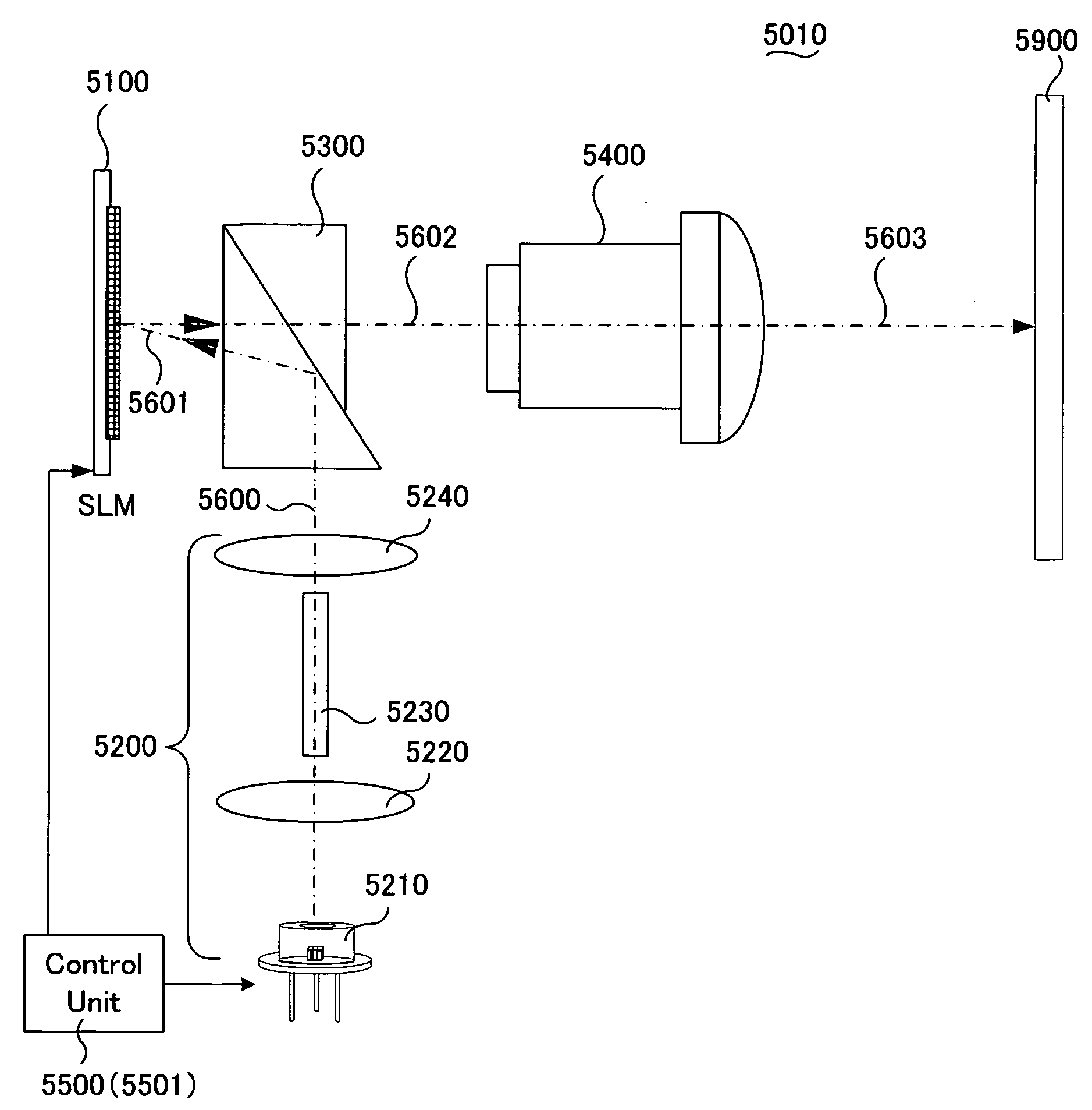
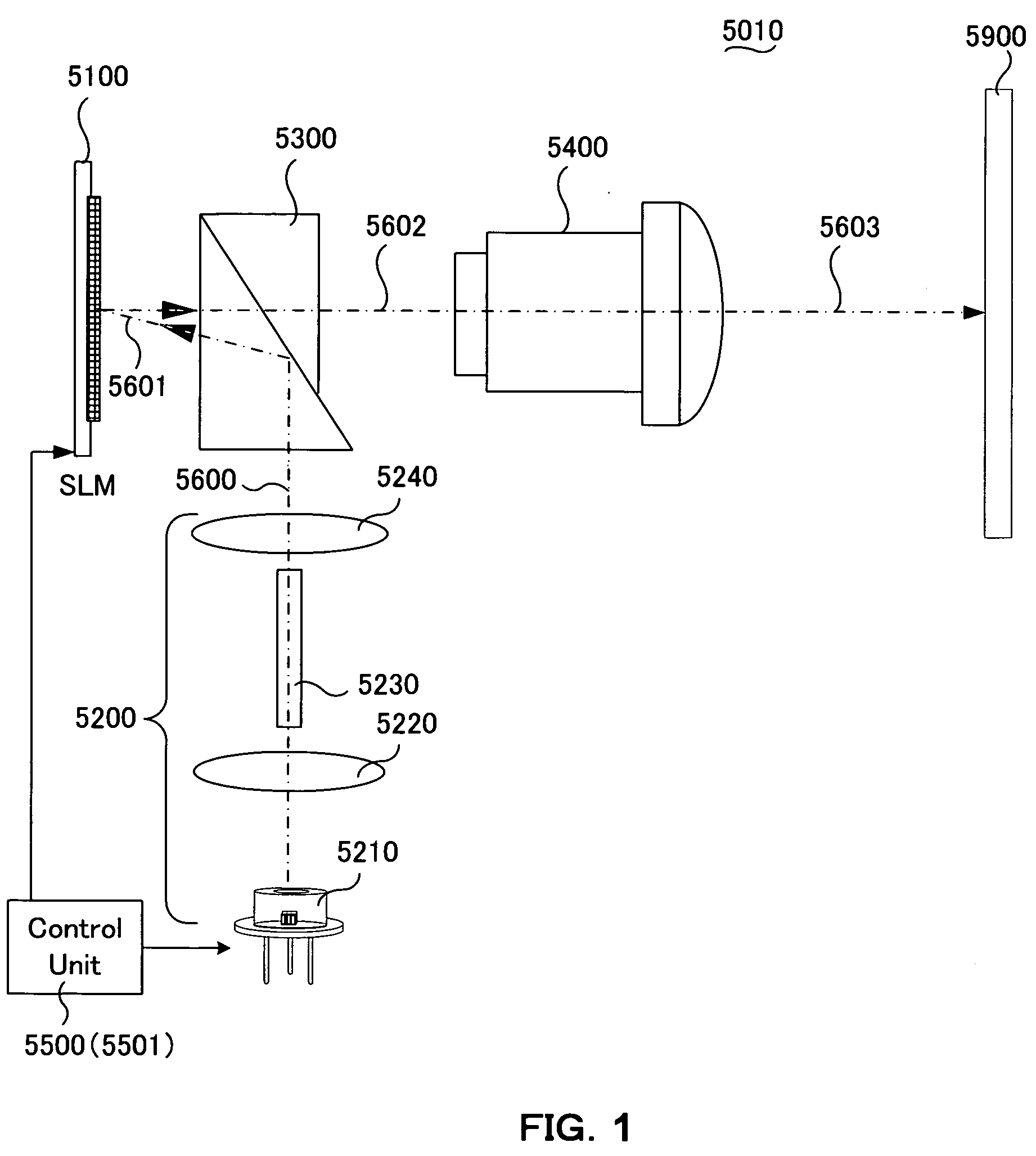
[0162]A projection apparatus according to the present embodiment may be implemented according the apparatuses described as a single-panel projection apparatus 5010, that includes the optical system as depicted in the above described FIG. 1 and the control system (i.e., the control 5500) as that depicted in the above described FIG. 3A. The image projection apparatuses carry out a projection display of a color image by implementing a color sequential display method.

[0163]Specifically, the SLM controller 5530 of the control unit 5500 as that implemented by the projection apparatus 5010 generates a light source profile control signal 5800 based on the input digital video data 5700. The light source profile control signals are then inputted to a light source control unit 5560 through a sequencer 5540A.

[0164]The light sou...

embodiment 2

[0201]As described above, an image projection apparatus employs a spatial light modulator 5100 implemented as a mirror device. According to the present embodiment, the mirror device is configured to carry out a linear gray scale display that is different from a conventional display apparatus, such as a cathode ray tube (CRT) display.

[0202]Therefore, FIG. 19 illustrates a gamma correction; an input data γ curve 7700a is applied to a piece of input digital video data 5700 at the transmission source (i.e., where the imaging is carried out). Assuming a display on a CRT, as shown in FIG. 19, a projection apparatus comprising a display device other than a CRT is required to restore the characteristic of a gray scale display to the original state (e.g., a conversion line 7700L for performing a linear conversion of the input data signal and brightness signal). This is done by means of a correction such as a gamma correction curve 7700b, or by a variety of gamma corrections in accordance wit...


PUM


Abstract

The present invention provides a display apparatus, comprising: a light source; at least one spatial light modulator for modulating a luminous flux emitted from the light source; and a controller for processing inputted video image information and for controlling the light source and spatial light modulator, wherein the controller controls the light source and spatial light modulator so that the light source performs pulse emission for a period shorter than a period in which the spatial light modulator is controlled under a modulation state.

Description

CROSS REFERENCE TO RELATED APPLICATIONS[0001]This application is a Non-provisional application claiming a Priority date of Oct. 2, 2007 based on a previously filed Provisional Application 60 / 997,476 and a Non-provisional patent application Ser. No. 11 / 121,543 filed on May 3, 2005 issued into U.S. Pat. No. 7,268,932. The application Ser. No. 11 / 121,543 is a Continuation In Part (CIP) Application of three previously filed Applications. These three Applications are Ser. No. 10 / 698,620 filed on Nov. 1, 2003, Ser. No. 10 / 699,140 filed on Nov. 1, 2003 now issued into U.S. Pat. No. 6,862,127, and Ser. No. 10 / 699,143 filed on Nov. 1, 2003 now issued into U.S. Pat. No. 6,903,860 by the Applicant of this Patent Applications. The disclosures made in these Patent Applications are hereby incorporated by reference in this Patent Application.BACKGROUND OF THE INVENTION[0002]1. Field of the Invention[0003]The present invention relates generally to the system configuration and methods for controllin...

Claims


Application Information

Patent Timeline
IPC IPC(8): H04N5/74
CPCG02B26/0833G02B27/1026G02B27/1033G09G3/2077G09G3/3406G09G2320/0653G09G2310/0237G09G2320/0633G09G2320/064G09G2320/0646G09G3/346
Inventor ENDO, TAROARAI, KAZUMAMAEDA, YOSHIHIROISHIL, FUSAO
Owner OLYMPUS CORP
Why Eureka
Try Eureka