Dual function fuel injector with tunable intra-port air & fuel flow control

a fuel injector and intra-port air technology, applied in liquid fuel feeders, machines/engines, mechanical equipment, etc., can solve the problems of reduced top end performance, complicated and costly implementation and production, and extremely limited potential as an aftermarket product, so as to improve the fuel delivery and achieve precise intensity and/or angle and/or direction.

Active Publication Date: 2018-07-19
XCENTRICK INNOVATIONS LTD
View PDF14 Cites 5 Cited by
  • Summary
  • Abstract
  • Description
  • Claims
  • Application Information

AI Technical Summary

Benefits of technology

[0006]The typical modern IC engine port fuel injection system utilizes an electromagnetic solenoid based port fuel injector. Such systems generally allow for ease of removal and installation of the port fuel injectors onto the top of the intake manifold. Such systems generally allow for a significant range of free angled rotation of the fuel injector along its center longitudinal axis in the fully seated and installed position without impacting its performance or causing leaks or any other negative issue. By attaching a flow diverting blade to the intra-port tip end of the fuel injector it is possible to take advantage of the typical fuel injector externally selectively variable rotational angle range of motion to allow for ease of manual selection of the angle of the intra-port blade and create the precise intensity and / or angle and / or direction of air and fuel swirl desired for each individual cylinder therein. Further the opportunity to improve the fuel delivery created with the here disclosed invention.

Problems solved by technology

The goal is to find the perfect balance between the intensity and / or angle of swirl generated and a reduction in the high end flow dimension resulting in reduced top end performance.
These devices are designed to allow for on the fly variability and are very complicated and costly to implement and produce.
These types of devices require major redesign of existing production engines and would therefore have extremely limited potential as an aftermarket product.

Method used


Image

  • Dual function fuel injector with tunable intra-port air & fuel flow control
  • Dual function fuel injector with tunable intra-port air & fuel flow control
  • Dual function fuel injector with tunable intra-port air & fuel flow control

Examples


Embodiment Construction

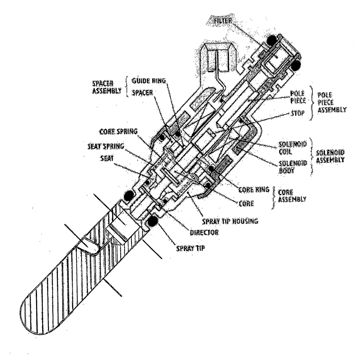
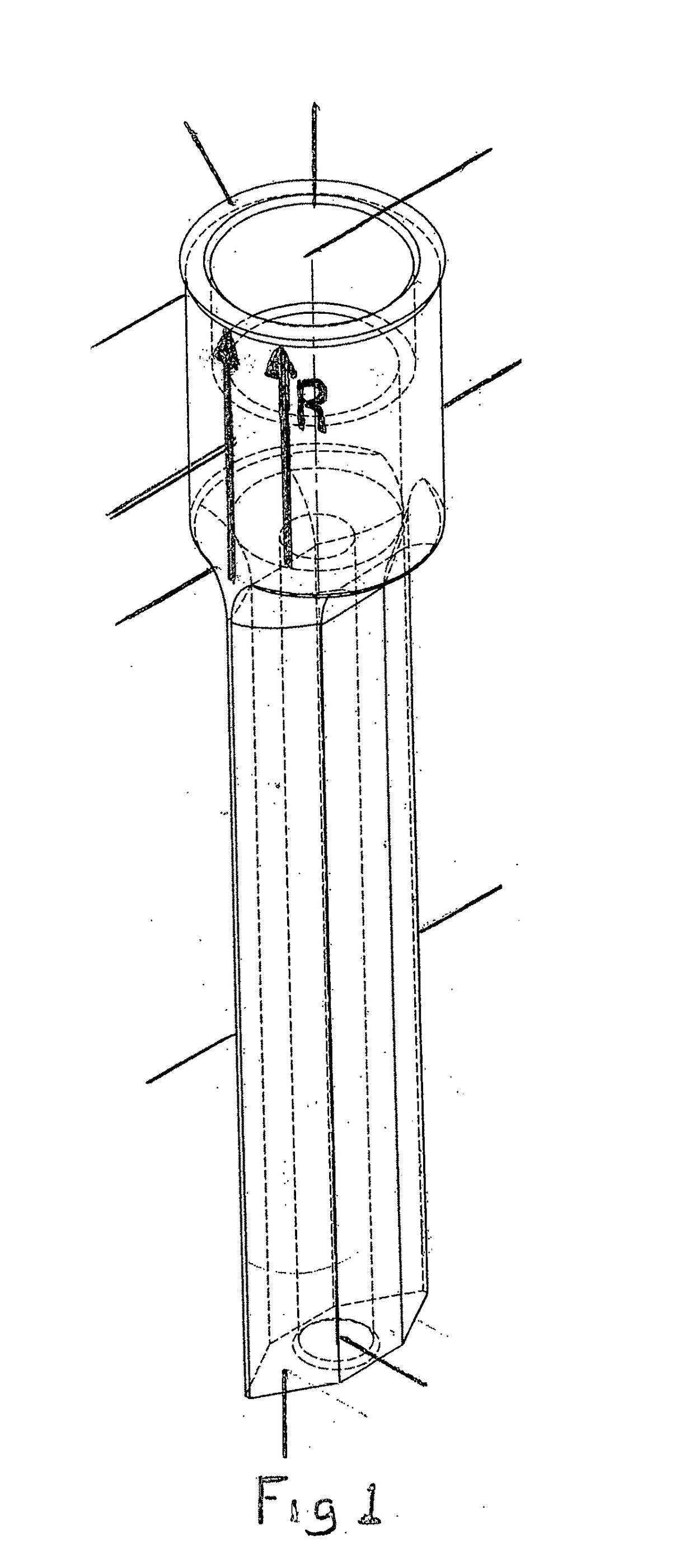
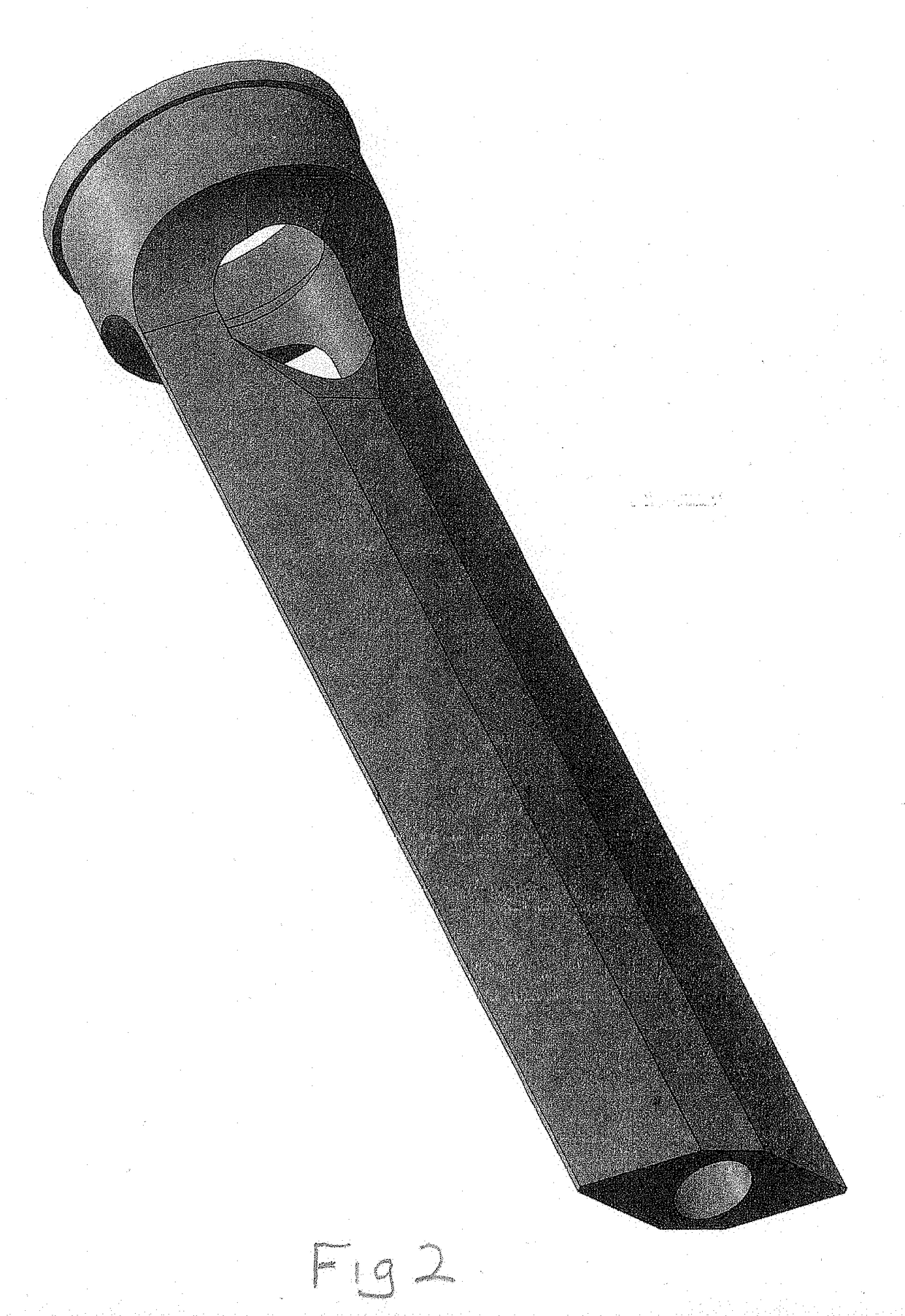
[0013]A dual function fuel injector as disclosed herein can be accomplished either by integrating the flow diverting blade as integral to the final construction of a typical port fuel injector as depicted in FIG. 5, OR, through the application of a separate flow diverting blade unit specifically designed for retro-fit onto an existing port fuel injector as depicted in FIGS. 1-4.

[0014]In preferred embodiment No. 1 a retro-fit version of a blade unit includes a small protruding lip is incorporated at the top end of the collar (FIGS. 1-4) in order to disallow the blade assembly to become fully disengaged with the fuel injector and / or fall into the intake port.

[0015]To aid in the retro-fit installation of the blade unit the collar ID section includes at least two (2) different internal dimension sections and is stepped as depicted in FIGS. 1 & 3. A substantial portion of the initial ID section from the open top end is sized to allow snug slip on application to a fuel injector's nozzle t...


PUM


Abstract

In the preferred embodiments an air flow diverting blade is integral to a base that doubles as a collar designed to coaxially attach to the tip end of a typical port fuel injector for internal combustion engines.Upon simple manual manipulation of the set rotational angle of the typically externally exposed portion of the port fuel injector along its longitudinal axis, as typical modern port injection systems allow after installation, the angle of the intra-port flow diverting blade can be selectively varied to either straighten existing swirl and increase top end flow, or, introduce lateral directional swirl to whatever desired angle and intensity in either direction is desired. The functional use of a typical port fuel injector is thereby elevated to a dual function of both tunable fuel and air flow control at the point of induction into a combustion chamber without any modification to existing engine designs or their engine management control systems employed therefore. The flow diverting blade can be configured to divert flow around the intake valve stem, guide and guide boss in such a manner to optimize the overall flow dimension of the induction system of a typical internal combustion engine. The flow diverting blade also provides an effective means by which the proximity and angle of fuel injection, relative to the combustion chamber, can be altered and improved as desired. The flow diverting blade also provides an effective means by which a modest increase in effective fuel injector nozzle pressure and fuel vaporization can be realized during periods of high load.

Description

BACKGROUND[0001]Swirl air flow generation within the induction tract of the typical Internal combustion (IC) engine has long been recognized as a means to enhance certain desirable performance aspects therein. The goal is to find the perfect balance between the intensity and / or angle of swirl generated and a reduction in the high end flow dimension resulting in reduced top end performance. Further, the optimal preferred lateral direction of the swirl, from either the left or the right, varies with different IC engine configurations. It has also been determined that devices that attempt to generate swirl upstream of the intake valve deliver minimal to negative overall performance results.[0002]Several attempts to create selectively variable intra-port swirl generators have been made such as Sakurai et al, U.S. Pat. No. 4,700,669 to Toyota and Khalighi et al, U.S. Pat. No. 4,827,883 to GM. These devices are designed to allow for on the fly variability and are very complicated and cost...

Claims


Application Information

Patent Timeline
Patent Type & Authority Applications(United States)
IPC IPC(8): F02M61/16F02M61/18F02M69/04F02M51/06
CPCF02M61/162F02M61/1813F02M69/047F02M51/061F02M61/145F02M61/18
Inventor HUFF, REGGIO DWAYNE
Owner XCENTRICK INNOVATIONS LTD
Why Eureka
Try Eureka