System and method for loadbalancing in a network environment using feedback information

a network environment and feedback information technology, applied in the field of communication, to achieve the effect of accurate distribution of work, improved loadbalancing capacity, and improved user experien

Active Publication Date: 2006-03-28
CISCO TECH INC
View PDF34 Cites 37 Cited by
  • Summary
  • Abstract
  • Description
  • Claims
  • Application Information

AI Technical Summary

Benefits of technology

[0004]From the foregoing, it may be appreciated by those skilled in the art that a need has arisen for an improved communications approach that provides for more accurate loadbalancing based on accurate feedback information provided by communications between two end points or nodes. In accordance with one embodiment of the present invention, a system and method for loadbalancing are provided that greatly reduce disadvantages and problems associated with conventional loadbalancing techniques.
[0007]Certain embodiments of the present invention may provide a number of technical advantages. For example, according to one embodiment of the present invention a communications approach is provided that allows a loadbalancer to more accurately distribute work to multiple network nodes. This is a result of a loadbalancer that can make loadbalancing decisions based on feedback information received from any one or more of the available network nodes. The loadbalancer may then direct a create request to a network node that is most capable of handling the incoming flow. For example, the loadbalancer may recognize that a given network node with the least number of current sessions should receive the flow. By referencing a data structure or a table that maintains such information, effective loadbalancing is achieved as data may be properly directed to network nodes that are most capable of accommodating traffic flows. Moreover, the improved capacity of the loadbalancer provides a better user experience as connection requests need not be constantly retried in order to connect to an alternate server. This may further eliminate any need to run back off timers or delay a given connection further.

Problems solved by technology

This is a result of a loadbalancer that can make loadbalancing decisions based on feedback information received from any one or more of the available network nodes.

Method used


Image

  • System and method for loadbalancing in a network environment using feedback information
  • System and method for loadbalancing in a network environment using feedback information
  • System and method for loadbalancing in a network environment using feedback information

Examples


Embodiment Construction

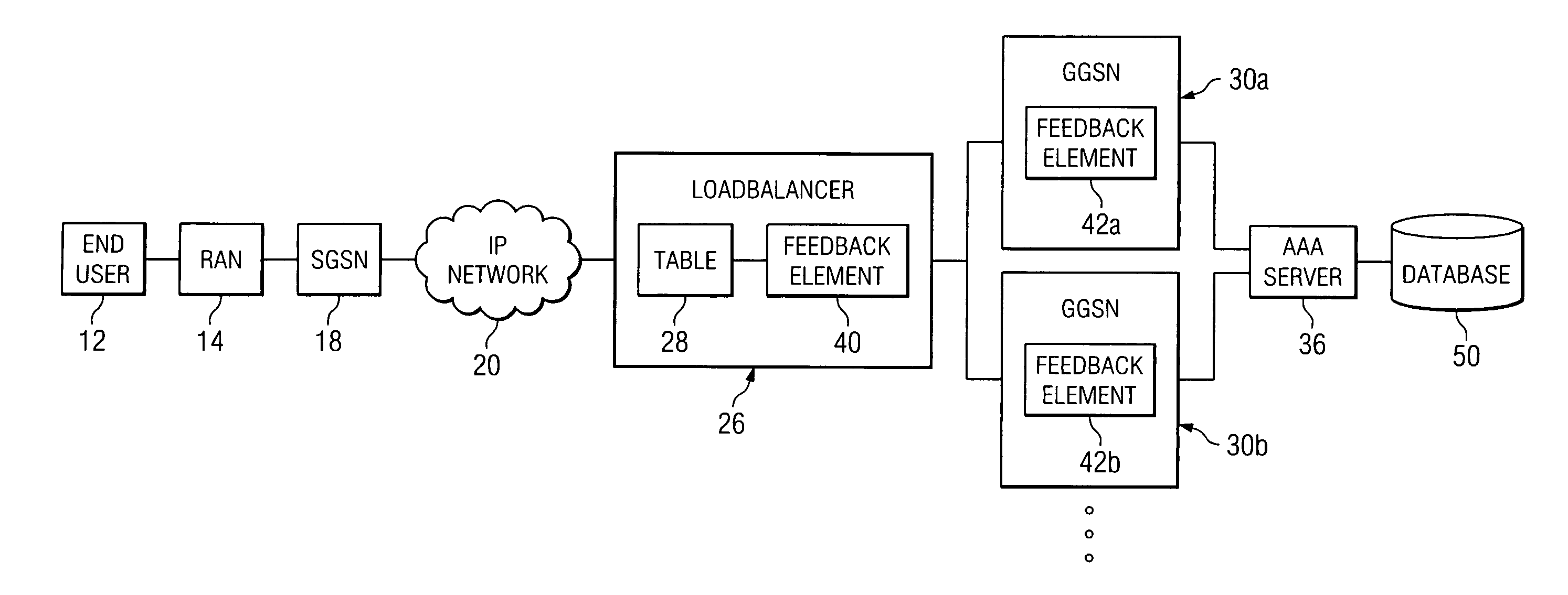
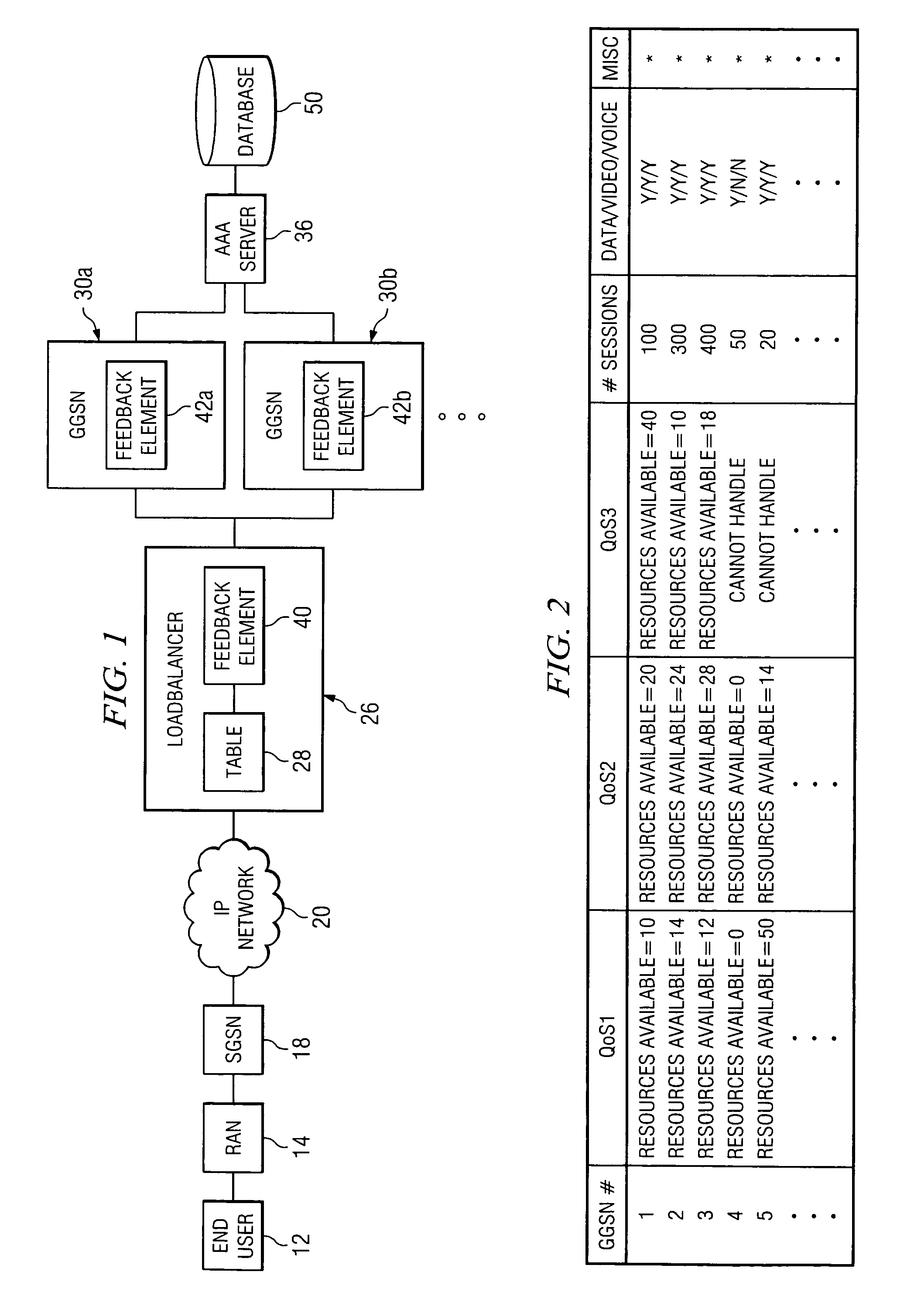
[0013]FIG. 1 is a simplified block diagram of a communication system 10 for communicating data in a network environment. Communication system 10 may include an end user 12, a radio access network (RAN) 14, a serving general packet radio service (GPRS) support node (SGSN) 18, and an internet protocol (IP) network 20. Additionally, communication system 10 may include a loadbalancer 26 (that may include a table 28) and multiple gateway GPRS support nodes (GGSNs) 30a–b. Communication system 10 may further include multiple feedback elements 40, 42a, and 42b. Communication system 10 may also include an authentication, authorization, and accounting (AAA) server 36 and a database 50.

[0014]FIG. 1 may be generally configured or arranged to represent a 2.5G communication architecture applicable to a Global System for Mobile (GSM) environment in accordance with a particular embodiment of the present invention. However, the 2.5G architecture is offered for purposes of example only and may altern...


PUM


Abstract

A method for loadbalancing in a network environment is provided that includes receiving a request from an end user for a communication session at a central node. The method further includes identifying a selected one of a plurality of network nodes to facilitate the communication session for the end user based on feedback information provided by the selected network node. The feedback information is communicated from the selected network node and processed before making a decision to establish the communication session between the selected network node and the end user.

Description

TECHNICAL FIELD OF THE INVENTION[0001]This invention relates in general to the field of communications and, more particularly, to a system and method for loadbalancing in a network environment using feedback information.BACKGROUND OF THE INVENTION[0002]Networking architectures have grown increasingly complex in communications environments. In addition, the augmentation of clients or end users wishing to communicate in a network environment has caused many networking configurations and systems to respond by adding elements to accommodate the increase in networking traffic. Communication tunnels or links may be used in order to establish or to gain access to a network, whereby an end user or an object may initiate a tunneling protocol by invoking a selected location or a network node. The network node or selected location may then provide a platform that the end user may use to conduct a communication session.[0003]As the subscriber base of end users increases, proper routing and effi...

Claims


Application Information

Patent Timeline
Patent Type & Authority Patents(United States)
IPC IPC(8): H04L12/26H04L12/56H04L47/80
CPCH04L12/5695H04L67/1002H04L47/125H04L47/726H04L47/781H04L47/801H04L47/805H04L47/822H04L47/824H04L63/08H04L63/0892H04L63/10H04L67/1008H04L67/1029H04L67/1031H04L47/11H04L47/70H04L67/1001
Inventor CHANDWADKAR, ASHISH A.IYER, JAYARAMAN R.O'ROURKE, CHRIS
Owner CISCO TECH INC
Why Eureka
Try Eureka