Methods for determining characteristics of earth formations

a technology of earth formations and characteristics, applied in the field of subsurface earth formation investigation, can solve the problems of affecting the accuracy of the assessment of one or more formation characteristics, affecting the accuracy of the count rate, and being more difficult to compensate, so as to achieve accurate image of the borehole circumference

Inactive Publication Date: 2005-10-18
HALLIBURTON ENERGY SERVICES INC
View PDF19 Cites 37 Cited by
  • Summary
  • Abstract
  • Description
  • Claims
  • Application Information

AI Technical Summary

Benefits of technology

[0018]An advantage of the invention is that azimuthal information and standoff information is collected along with the energy data, enabling weighting the data within an azimuthal sector to compensate for perturbations in the data collected in a much more precise manner than the known systems. This enables compensation for variances in standoff that change with azimuthal tool position and from rotation to rotation. The ultimate measured characteristic is more accurate.
[0019]An additional advantage of the invention is that, because the data is associated with the angular position of tool, an accurate image of the borehole circumference can be developed. Incorporating angular position into the analysis enables the operator to see when the tool is passing through formation boundaries and the relative position of the tool to the boundary.
[0020]An additional advantage of the invention is that the information gathered during LWD can be used, for example, in geo-steering the drilling to direct the well to a target more accurately than would be possible with only geometric information of the type and resolution derived from surface seismic testing.
[0021]Furthermore, the invention provides embodiments with other features and advantages in addition to or in lieu of those discussed above. Many of these features and advantages are apparent from the description below with reference to the following drawing.

Problems solved by technology

The effectiveness of such methods ultimately affects the accuracy of the assessment of the one or more formation characteristics.
More substantial variations in standoff impact the accuracy of the count rate and are more difficult to compensate, particularly as the offset becomes large.
Irregular variations that occur when the tool walks in the borehole are difficult to compensate, especially when the standoff changes are large.
Such generalization by quadrant is not ideal for devising a borehole image nor a representative formation characteristic of the borehole.

Method used


Image

  • Methods for determining characteristics of earth formations
  • Methods for determining characteristics of earth formations
  • Methods for determining characteristics of earth formations

Examples


Embodiment Construction

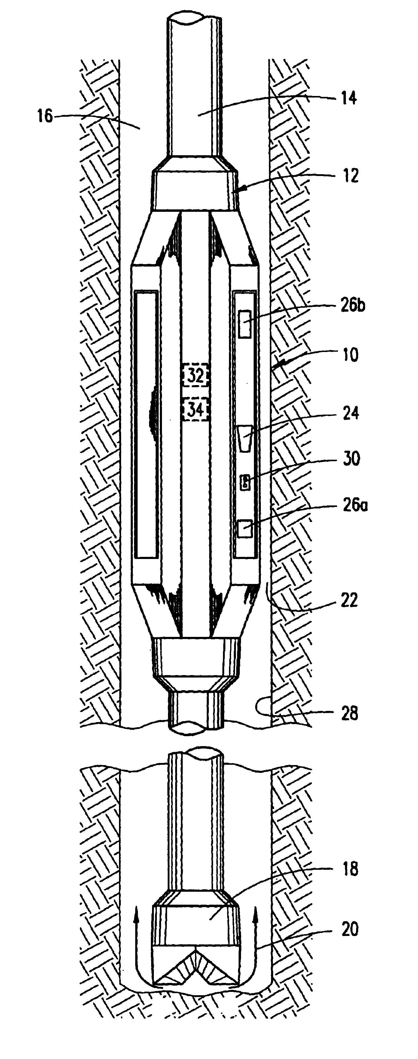
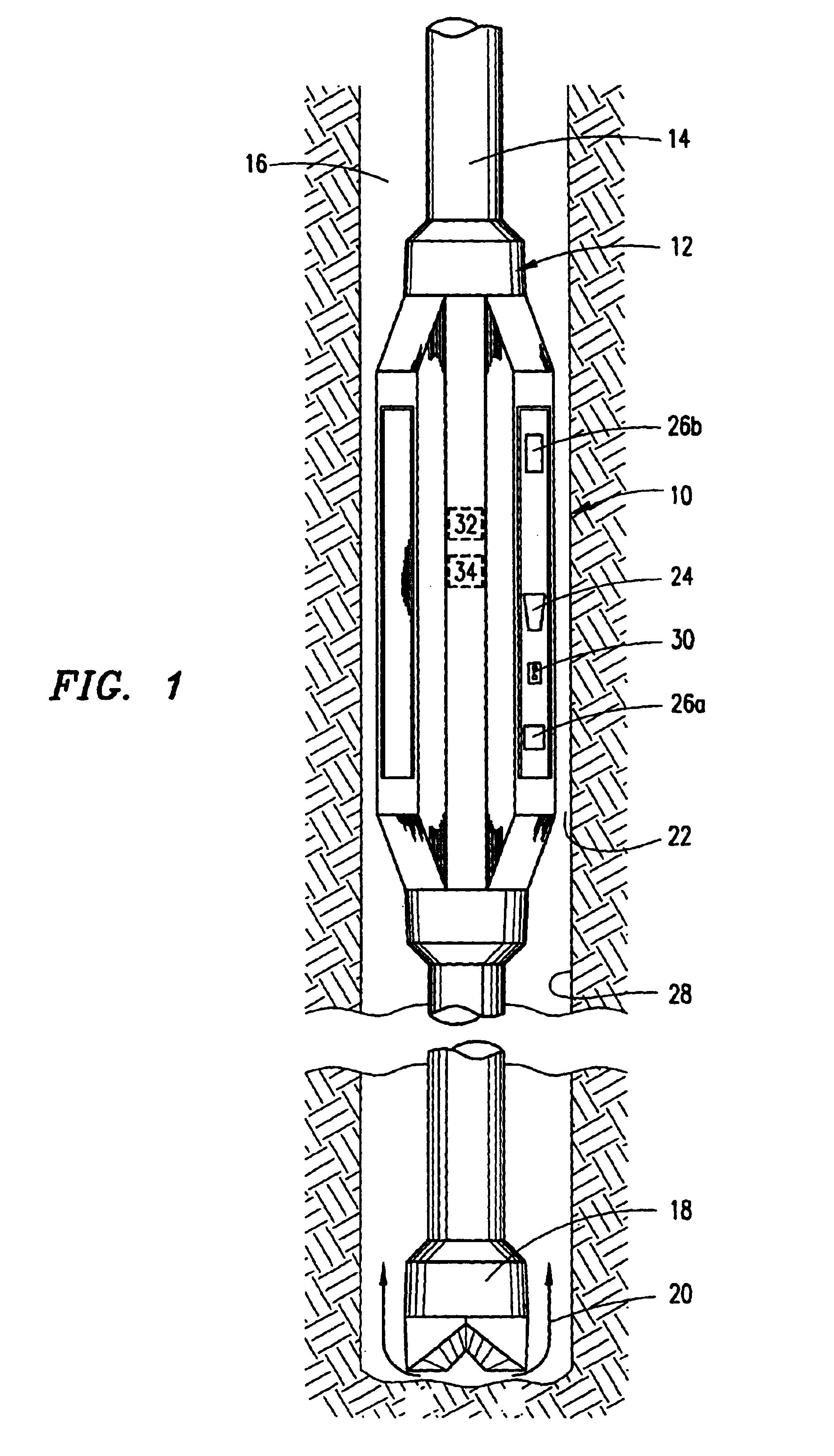
[0024]Referring first to FIG. 1, a logging while drilling (LWD) tool 10 is generally housed in a drill collar 12 that is threadingly secured in-line with a drill string 14. The drill string 14 is a tubular body extending from a drilling rig (not shown) into an earth formation, axially thorough a borehole 16. A drill bit 18 is secured to one end of the drill string 14. The drill string 14 is rotated to turn the bit 18, thereby drilling through the earth formation and forming the borehole 16. The borehole 16 may be drilled substantially vertical through the earth formation or may be drilled at angles approaching or at horizontal. A borehole 16 that is drilled at an angle other than vertical is generally referred to as being deviated. During the drilling operations, drilling mud 20 is pumped down from the surface through the drill string 14 and out of the bit 18. Drilling mud 20 then rises back to the surface through an annular space 22 around the drill string 14. Data from the LWD too...


PUM


Abstract

A method for measuring one or more characteristics of an earth formation wherebyenergy is emitted circumferentially about a borehole into the formation, and the amount reflected back is detected during a plurality of sample periods. The samples are grouped into two or more groups by the azimuthal sector in which the sample was collected. Within a group, each sample is mathematically weighted according to the standoff of the detector from the borehole wall when the sample was taken. Within a group, the weighted samples are summed to produce a weighted total amount of energy detected within a sector. The weighted total is then transformed into the one or more characteristics.

Description

[0001]This application is a continuation (and claims the benefit of priority under 35 USC 120) of U.S. application Ser. No. 09 / 970,370, filed Oct. 2, 2001 now U.S. Pat. No. 6,619,395. The disclosure of the prior application is considered part of (and is incorporated by reference in) the disclosure of this application.BACKGROUND OF THE INVENTION[0002]1. Field of the Invention[0003]The present invention relates to the investigation of subsurface earth formations, and more particularly to methods for determining one or more characteristics of an earth formation using a borehole logging tool.[0004]2. Description of the Related Art[0005]When drilling an oil and gas well, it is often desirable to run a logging while drilling (LWD) tool in-line with the drill string to gather information about the subsurface formations while the well is being drilled. The LWD tool enables the operators to measure one or more characteristics of the formation around the circumference of the borehole. Data fr...

Claims


Application Information

Patent Timeline
Patent Type & Authority Patents(United States)
IPC IPC(8): E21B49/00E21B47/00
CPCE21B47/00E21B49/00G01V5/12
Inventor SPROSS, RONALD L.
Owner HALLIBURTON ENERGY SERVICES INC
Why Eureka
Try Eureka