Cannula-based surgical instrument

a surgical instrument and cannula technology, applied in the field of cannulas, can solve the problems of increasing the length and risks of the operation, the endoscope lens is subject to the adverse conditions described, and many surgical procedures cannot be performed using a blunt dissection tip, so as to achieve the effect of reducing the risk of surgery, and accurate spraying

Inactive Publication Date: 2009-01-13
MAQUET CARDIOVASCULAR LLC
View PDF88 Cites 37 Cited by
  • Summary
  • Abstract
  • Description
  • Claims
  • Application Information

AI Technical Summary

Benefits of technology

[0006]In accordance with one embodiment of the present invention, a remote irrigation system is built into the cannula. In one embodiment, one of the legs which comprise the retractor of the present invention is hollow, and is attached to a spray nozzle disposed in the distal end of the retractor. The proximal end of the hollow leg is attached to a fluid input tube which selectively provides irrigation fluid under pressure for washing the endoscope lens. When extended slightly beyond the distal end of the cannula, the spray nozzle is positioned to direct the spray of irrigation fluid at an angle approximately normal to the endoscope lens. This provides for an extremely effective cleaning action, and minimizes the need for removal of the endoscope during surgical procedures for manual cleaning. Additionally, if the surgical site itself requires irrigation, the retractor is extended out of the cannula toward the area requiring irrigation, and an irrigation fluid can be sprayed directly on the site. Finally, as the spray is directed back toward the lens, the surgeon can visually adjust the extension of the retractor to accurately direct the spray toward the lens or surgical site.
[0007]In a further embodiment, the hollow leg moves within a lumen in the cannula in fluid-resistant sliding engagement, and the fluid input tube is coupled to this lumen. In this embodiment, the maximal outer dimension of a region of the hollow leg is slightly less than a maximal inner dimension of the lumen. The slip-fit, fluid-resistant coupling of the hollow leg within the lumen allows irrigation fluid to be introduced at the proximal end of the lumen by the fluid input tube without significant leakage past the sliding juncture of the hollow leg within the lumen.
[0008]In an alternate embodiment, the hollow leg includes a semi-rigid plastic tubing, and fits within an irrigation tube which lines the inside of the lumen. The fluid input tube attaches to the irrigation tube and extends out of the cannula handle for receiving irrigation fluid. The use of flexible, semi-rigid plastic tubes provides fluid seals throughout the irrigation system to minimize leakage. In a third embodiment, the cannula contains a separate irrigation lumen which has a spray nozzle disposed in a fixed position at its distal end. The spray nozzle is positioned within the cannula to allow the proper angle of incidence for the spray to effectively clean the lens. Finally, in another embodiment, the dissection cradle is supported by only one leg, and the lumen which previously held the second leg instead is fitted with a spray nozzle directed toward the endoscope lens. An embodiment is also disclosed in which a nozzle tube situated within a cannula lumen is selectively extensible responsive to the application of hydraulic pressure.

Problems solved by technology

However, many surgical procedures cannot be performed using a blunt dissection tip.
When the cannula end is open, the endoscope lens is subject to the adverse conditions described above.
This increases the length and risks of the operation.
However, having a cleaning system within the endoscope restricts the angle of incidence at which the cleaning fluid may be propelled toward the lens to almost parallel to the lens.
This results in a less effective cleansing action.
Also, since the spray is being directed parallel to the lens, the surgeon cannot see the spray source and it is therefore difficult to adjust the direction of the spray.
Additionally, in procedures using gas insufflation, the gas may dry out a target vessel or other surgical site.
However, conventional endoscope washing systems are not capable of providing both endoscope lens cleaning and remote surgical site irrigation.

Method used


Image

  • Cannula-based surgical instrument
  • Cannula-based surgical instrument
  • Cannula-based surgical instrument

Examples


Embodiment Construction

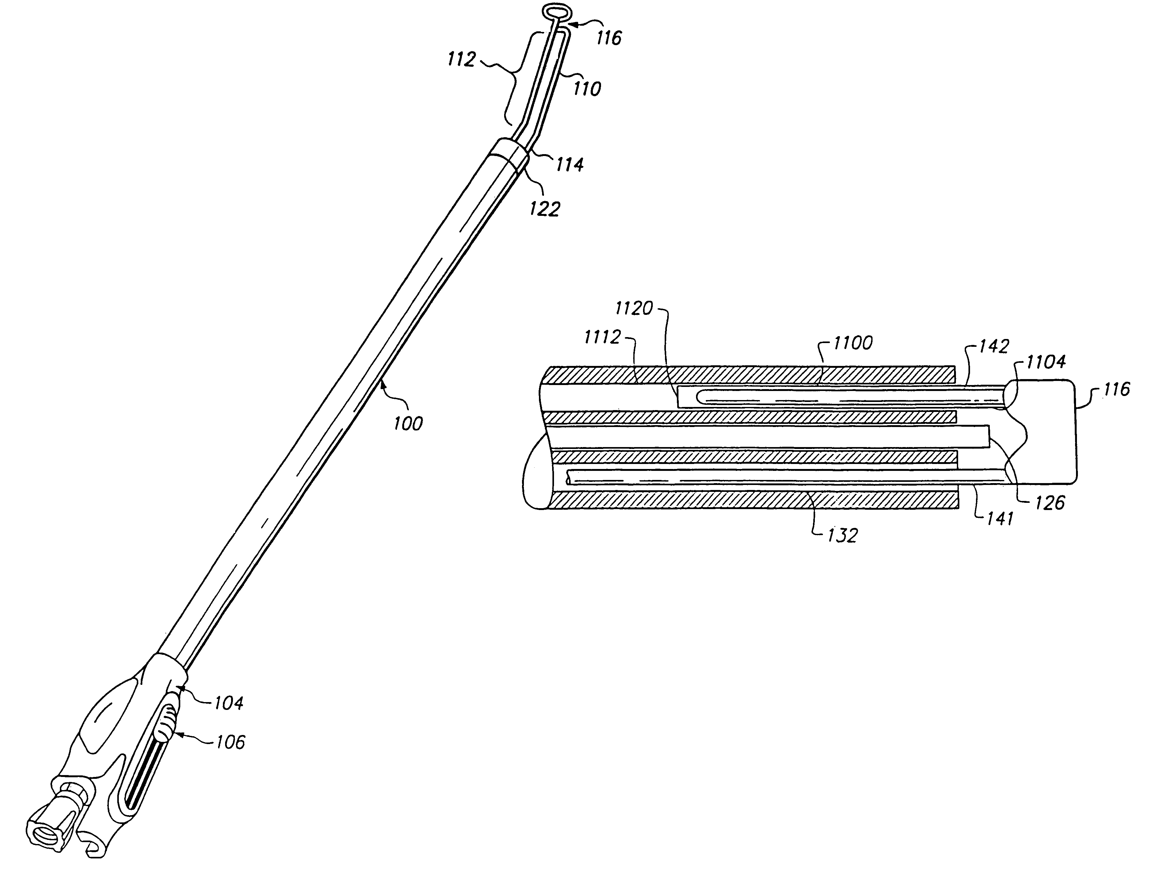
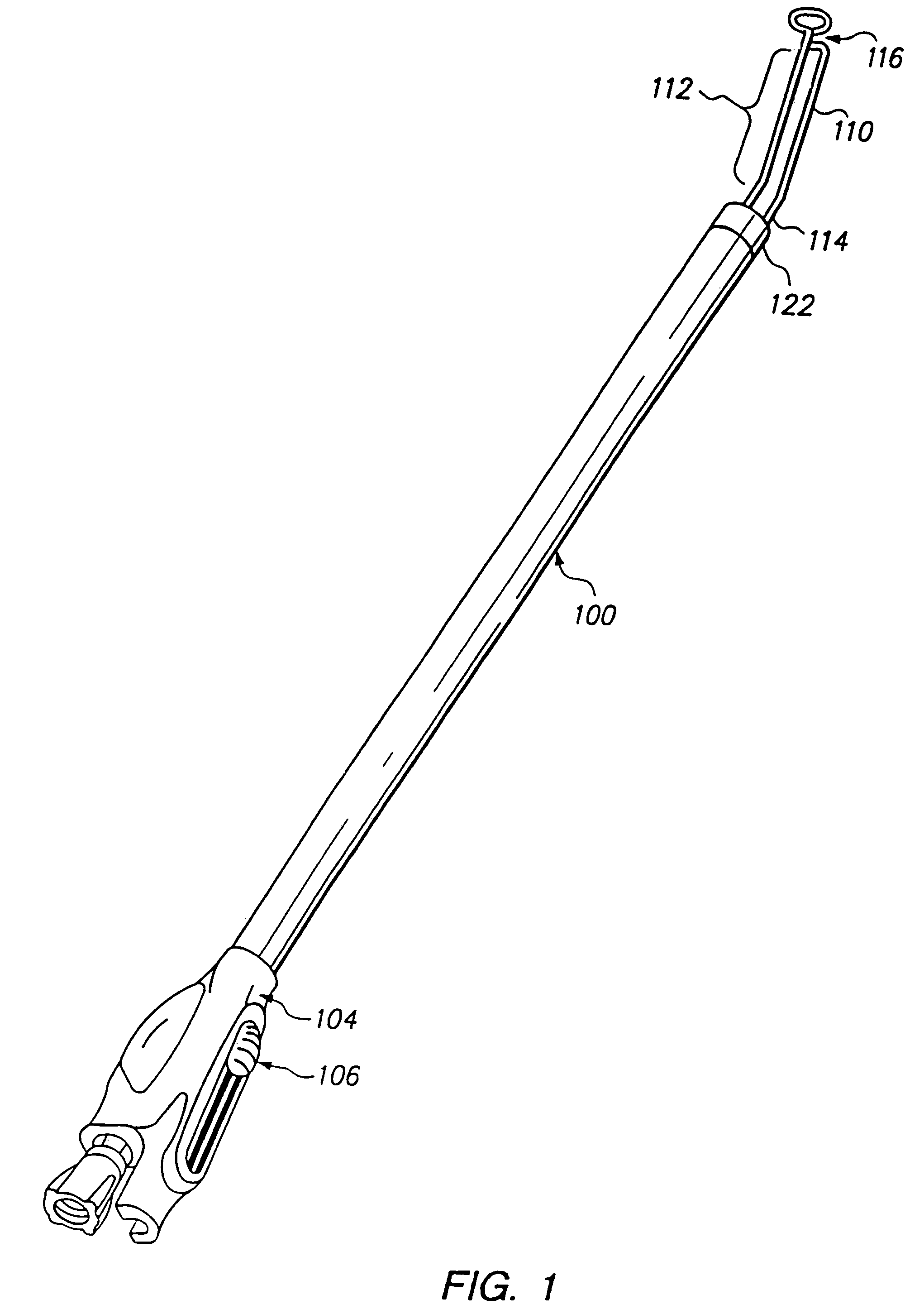
[0050]FIG. 1 illustrates a perspective view of a preferred embodiment of cannula 100 showing retractor 112 in an extended position. Cannula 100 includes an outer housing 102 of bioinert material such as polymed UD that may be approximately 12″ to 18″ in length. The proximal end of the cannula 100 is disposed in handle 104 that includes a button 106 which is coupled to retractor 112 for controlling the translational movement of retractor 112, as described in more detail below.

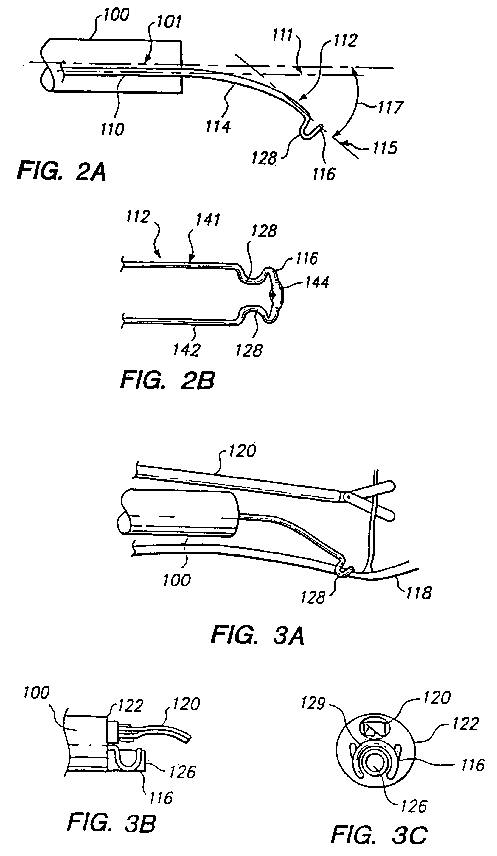
[0051]The distal end of the cannula houses a retractor 112, and optionally an endoscope 126 and a surgical tool 120, described below. FIG. 2a illustrates the retractor 112 in more detail. In one embodiment, retractor 112 is formed of resilient wire which has a smooth bend intermediate to a first portion 110 and a second portion 114 of the retractor. The retractor 112 is described as having two portions for ease of description, although the retractor 112 may be formed as an integrated structure. However, retracto...


PUM


Abstract

A retractor and a surgical tool are positioned within a cannula, and a dissection cradle of the retractor is positioned at the distal end of the cannula. The retractor includes a dissection cradle that is resiliently supported along an axis skewed relative to the axis of the cannula. The dissection cradle, in operation, is extended to cradle the target vessel, and the retractor may be fully extended to urge the vessel away from the axis of the cannula to isolate a side branch for exposure to a surgical tool. The retractor includes a hollow support and a spray nozzle disposed in the distal end of the retractor to form an irrigation system and lens washer that can be selectively positioned to direct the spray of irrigation fluid at a remote surgical site or at an endoscopic lens.

Description

RELATED APPLICATIONS[0001]This application is a continuation of application Ser. No. 10 / 773,770 filed on Feb. 6, 2004, now U.S. Pat. No. 6,975,957, issued on Dec. 20, 2005, which is a continuation of application Ser. No. 10 / 174,404 filed on Jun. 17, 2002, now abandoned, which is a continuation of application Ser. No. 09 / 634,132, filed on Aug. 8, 2000, now issued as U.S. Pat. No. 6,406,425, which is a continuation of application Ser. No. 09 / 227,244 filed on Jan. 8, 1999, now issued as U.S. Pat. No. 6,176,825, which is a continuation-in-part application of application Ser. No. 09 / 102,723 filed on Jun. 22, 1998, now issued as U.S. Pat. No. 5,895,353.FIELD OF THE INVENTION[0002]This invention relates to a cannula used for endoscopic surgery, and more particularly to a cannula and method for maintaining a clear visual field for an endoscope housed with the cannula.BACKGROUND OF THE INVENTION[0003]Endoscopic surgery allows a surgeon to perform safe and successful procedures because of the...

Claims


Application Information

Patent Timeline
Patent Type & Authority Patents(United States)
IPC IPC(8): A61B1/32A61B1/12A61B1/012A61B1/015A61B1/018A61B17/00A61B17/02A61B17/28A61B17/32
CPCA61B1/313A61B17/00008A61B17/0218A61B2017/00292A61B2017/003A61B2017/00778
Inventor CHIN, ALBERT K.LUNSFORD, JOHN P.CHANG, TENNYBAXTER, JEFFREY W.
Owner MAQUET CARDIOVASCULAR LLC
Why Eureka
Try Eureka